INA331IDGKT is not available in ORCAD 16.3. So, I have created its library file & symbol in model editor by using its model file. But it is not working properly in my circuit.
It is facing convergence problem. Any kind of help will be appreciated.
This thread has been locked.
If you have a related question, please click the "Ask a related question" button in the top right corner. The newly created question will be automatically linked to this question.
INA331IDGKT is not available in ORCAD 16.3. So, I have created its library file & symbol in model editor by using its model file. But it is not working properly in my circuit.
It is facing convergence problem. Any kind of help will be appreciated.
Hi, Abhratanu,
I am moving this thread to the Precision Analog forum where the responsible apps engineers will get back to you.
-d2
Hi Abhratanu,
I just checked the INA331 simulation model using TINA PSpice and it simulated just fine. I don't have ORCAD so I can't check the circuit with that particular PSpice simulator. Can you provide a PDF of the circuit and conditions you are attempting to simulate? There may be something about your circuit, or set up conditions, that the simulator doesn't like. Non-convergence is the most commonly encountered problem with PSpice simulators and sometimes a setting, or two, will resolve the issue.
Regards, Thomas
PA - Linear Applicaitons Engineering
Hi Thomas,
For testing the model file of INA331, I drew a circuit of gain 5 in TINA simulator. But output voltage was varying when I changed supply voltage of INA331.
A snapshot of my circut with its output window has been attached below.
Here, Vin+ = 2.56v; Vin- =1.198v;
V- is connected to ground;
Ref pin is open;
Shutdown(EN) pin is connected to supply voltage;
RG is connected to Output;
Output voltage comes 3.55v when, V+ = 4.5v;
Output voltage comes 4.05v when, V+ = 5v
Please suggest me to get proper output from this circuit.
Thanks and regards,
Abhratanu Sarkar
Hello Abhratanu,
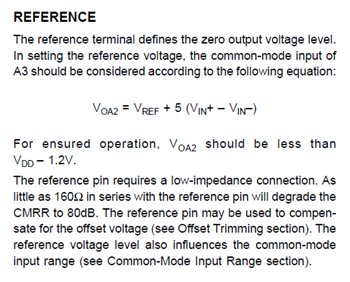
The issue with your INA331 simulation circuit is not related to the simulator or model, but the way the INA331 has been set up in the circuit. By allowing the REF pin to float the inverting input of INA331 A1 takes on the same common model voltage as the A1 non-inverting input. This connection becomes the Vin- (pin 2) to the outside world where you have 1.198V applied. The is common mode voltage level in conjunction with the differential voltage between the two INA331 inputs results in a voltage level where the amplifier output level saturates at its maximum output level. This can be easily seen from the datasheet information:

With Vref taking on the Vin- level of 1.198V, a differential voltage of 1.362V (2.56V - 1.198V), and the INA331 minimum gain of 5x, the amplifier output is attempting to swing to a level of 8.0V. This level cannot be attained with the supply set to 4.5V, or 5V. The level you are seeing at the output is the maximum swing level at the specific supply level.
Adjust your common mode, or REF voltage, such that the output is operating in the linear region and your circuit should simulate without any problems.
Regards, Thomas
PA - Linear Applications Engineering
That is why you see it change when you change the supply voltage change.