This thread has been locked.

If you have a related question, please click the "Ask a related question" button in the top right corner. The newly created question will be automatically linked to this question.

OPA855: Transimpedance amplifier consisted with OPA855 has spikes.

Part Number: OPA855

Hello, I'm using OPA855 for TIA(transimpedance amplifier) with avalanche photodidoe.

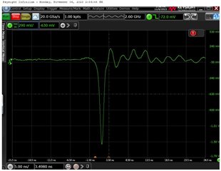
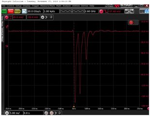
However my TIA circuit has the spikes with laser signals.

(I'm using laser diode '905D1S09S', Laser components. And laser diode driver 'PCO-7114-22-2A')

How can i reject those of spikes.
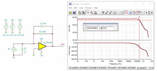
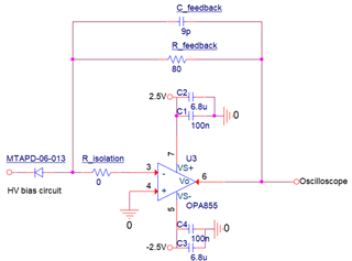
Circuit diagram

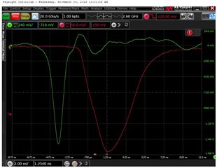
Spikes image (Oscilloscope with 50ohm mode)

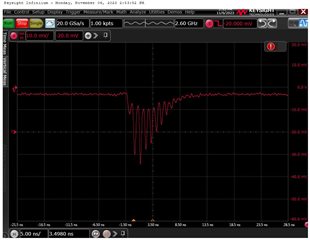
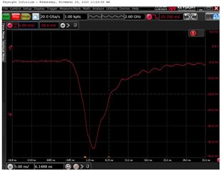
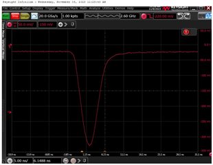
current monitor image of laser diode driver

  • Hi,

    The instability you are seeing on the output is expected based on the configuration of your circuit. The OPA855 is a decompensated amplifier that is stable for gains of 7 or larger. In order for the TIA to have a stable configuration, you need to have a high-frequency noise gain of 7V/V or larger. The high-frequency noise gain is found by 1+(Ctot/Cf) where Ctot=Cpd+Ccm+Cdiff.

    The photodiode you are using has a capacitance of 1.2pF and the input capacitance of the OPA855 is 0.8pF, meaning Ctot is 2pF. Therefore, for the amplifier to operate stably, Cf must be 333fF or smaller. This article (link) explains the calculations further. It also walks through determining Cf and Rf to set the pole and zero of the noise gain curve so that the TIA is stable.

    I would recommend simulating the circuit, including running a stability analysis, to check the feedback resistor and capacitor values for your circuit. I have attached TINA simulations below that you can use to run these simulations.

    OPA855_transient_E2E.TSC

    OPA855_stability_E2E.TSC

    Please let me know if you have any other questions.

    Thanks,

    Nick

  • Thank you for your help. I try again with 100fF feedback capacitor.

    Some of spikes are reduced but three or four spikes still remain.

    Initially, I think it look likes reflection but there isn't place for reflections with 2ns delay.

    Is there another reasons for spike except stability or reflection?

    Or, is that still stability problem?

  • Hi,

    Can you try increasing the value of the feedback resistor as well? I am unsure of what the input current range and frequency you are using. Ideally though, if you could test a feedback resistor of around 6kohms, as that is a tested feedback resistor value on the datasheet.

    I am suspicious that the small feedback resistor is still causing instability. When I run a stability analysis with the feedback resistor of 80 ohms and the feedback capacitor of 100fF, the model shows instability. But if I increase the feedback resistor, to say 6kohms, the model shows stability. This has to do with the location of the pole and zero created by the feedback resistor and feedback capacitor.

    Thanks,

    Nick

  • Hi, I don't have TINA, I try it with demo version. but OPA855 didn't run in demo ver. So I will try with OrCAD PSpice later. Thanks about your advise.

    Also I try with feedback resistor of 6.04kohms. Then, I can get a single pulse which has wide pulse width.

    Image1 with 5.5F (1/10^5.5 optical filter)

    Image2 with 4.3F (1/10^4.3 optical filter)

    The reason why i think pulse width is wide:

    I use laser diode '905D1S09S' which has threshold current of 600mA.

    and laser diode driver which has current monitor of 20V/A. (It means laser diode's threshold voltage is 1.2V)

    I comprehend next image means 'TIA get a pulse has pulse width of about 1ns'

    Channel 2: current monitor with 20V/A, Channel 4: TIA's output with 50 ohm mode osciloscope

    I think that single pulse is made with amplified spikes.

    If my comprehension is wrong, can you give me advise(why pulse width is not 1ns but 5ns~7ns )

    I can use that pulse for LiDAR, but I'm curious...

    Thank you

  • Hi, 

    I believe that the reason you are seeing a wider pulse width is that you are starting to reach some bandwidth limitations. Running an AC Analysis with a feedback resistor of 6.04kohms and a feedback capacitor of 100fF, the bandwidth is about 369 MHz. This means that the rise time of the output pulse will be about 1 ns (tr = 0.35 / BW). 

    Therefore, using those feedback resistor and capacitor values will cause a wider pulse width than 1 ns. By reducing the feedback resistor, the bandwidth will increase. However, using too small of a feedback resistor value will cause instability like you were seeing before. 

    If you need to decrease the pulse width, I recommend running a stability analysis and transient analysis to see the behaviors of reduced feedback resistor values. Also to note, these simulations do not factor in the effects of any stray PCB capacitance which could also reduce the bandwidth more as well. 

    Thanks,

    Nick

  • Hi, I solve my problem. 

    First, I solve stability problem with your kind advise!

    Secondly, I confused laser diode driver's current monitor unit. It was 20A/V not 20V/A. It means my laser diode has threshold current of 800mA(oscilloscope will display 40mV not 1.2V what i said). So, laser diode shoot multiple pulse with multiple current. I adjust high voltage of laser diode driver and i can get a single pulse.

    I appreciate for your help!

    Thanks

  • Hi,

    I'm glad I could assist you and that you were able to figure out the multiple pulse issue. I will close this thread. If you have any other questions, please feel free to respond to this thread or open a new E2E thread.

    Thanks,

    Nick