This thread has been locked.

If you have a related question, please click the "Ask a related question" button in the top right corner. The newly created question will be automatically linked to this question.

INA116PA Instrumentation amplifier troubleshooting

Other Parts Discussed in Thread: INA116

Hi all,

I recently purchased a few INA116PA instrumentation amplifiers to amplify a slowly oscillating (period = 140s, amplitude = 60mV) signal taken from a chemical cell for a chemistry experiment.  Right now I'm trying to get started with the amplifier, just seeing if I can amplify a DC voltage from a variable voltage DC power supply.  I've hooked everything up according to the datasheet but I don't get any amplification; the largest output I can get out of the amplifier is 3V, even though my power supply is +-16V.  The output signal is also unstable, oscillating rapidly between 0 and 3V.  Is there a correct procedure anyone can recommend for getting started with this amp?  I can include a schematic of the circuit I'm using if that's helpful.

Thanks,

Sam Kenny

University of Minnesota

  • Hi Sam,

    We discussed this in a previous posting. We should see a detailed schematic of your setup to help diagnose the issues. I'm sure we can get it operating properly. What is the frequency of the oscillations?

    For starters, be sure you have power supply bypass capacitors close to the amplifier. Also, be sure the connections to the gain-set resistor are short.

    Regards, Bruce.

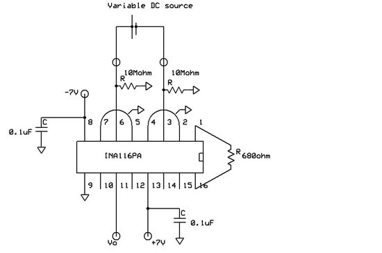
  • Here's the schematic; I think the power supply might be the issue.  It's not a very good one, and it'll go from +3/-12V to +7/-7V relative to ground in the circuit (Disregard what I said about it being a +/-16V supply in my initial post).  I'm looking into buying a good, accurate +/-15V power supply, which I think will help.  I did recently get some amplification with this setup, but it was with a gain of around 10, not 100 like I expected with this resistor.  I have this set up on a breadboard right now, which I think could be affecting the gain.  Any problems with this setup?  Anything else to consider?  Any help would be great.

  • Sam,

    The guard pins, 5 & 7, 2 & 4, should not be connected to ground. They should be allowed to float to their own potential, which will be very close to the input voltage of its associated input terminal. Each input guard must float independently so don't connect pin 4 to pin 5.

    I believe that you should remove one of the 10M resistors. With two resistors, you will load your cell with 10M. The purpose of this type of amplifier in this application is to avoid any significant loading of the cell and minimize charging the cell with input bias current. The input bias current of the INA116 is extremely small.

    For this arrangement, one of the inputs can be grounded, shorting out the remaining 10M resistor. You described another circuit in your earlier post where the second input goes to a potentiometer, but that's for later, I guess.

    Check your supply voltage relative to ground and let me know the frequency of any remaining oscillations.

    Regards, Bruce

  • Hi Bruce,

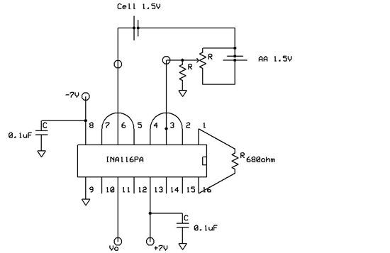
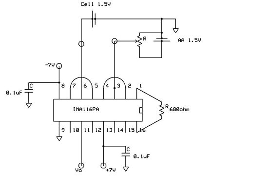
    Here are the two different setups I used to offset the cell's baseline voltage:

    My question is whether it's better to ground the input or ground the cell?  Or is there a better way to offset the voltage?

  • Sam,

    I think it would be better to ground one side of the cell as you've shown in the second diagram. I think you are less likely to have noise pickup this way.

    I suggest that you add a capacitor from the wiper of the potentiometer to ground. This will filter noise from the potentiometer--Johnson noise, as well as noise produced by the noisy contact resistance as you make adjustment. I don't know the value of your potentiometer but something like a 0.1uF should be okay.

    Regards, Bruce.