This thread has been locked.

If you have a related question, please click the "Ask a related question" button in the top right corner. The newly created question will be automatically linked to this question.

XTR111: XTR111

Part Number: XTR111
Other Parts Discussed in Thread: DAC8563, ISO7341C, MSP430F67791A, XTR300, DAC8771, ISO7721, ISO7741, AMC3301, OPA197, AMC3302, TINA-TI, LM7705
Hi 
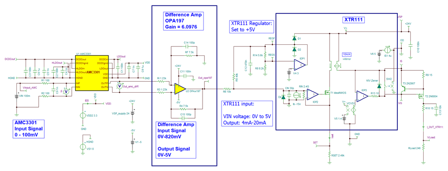
I am looking to build a signal converter/ isolator device that converts mV signal from the shunt to suitable PLC's input.
Requirements: 
  • Input/Output Isolation > 2.5kVrms
  • Nominal Operating Voltage= 24VDC
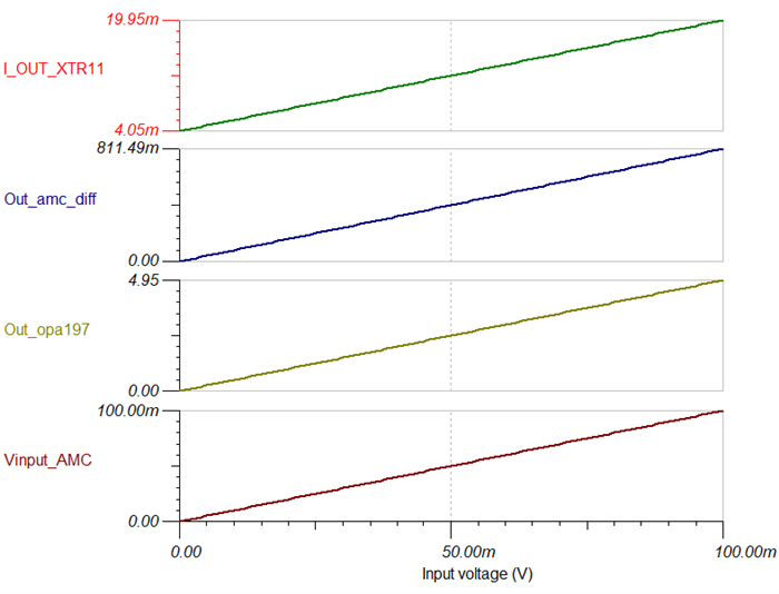
  • Input from the shunt  can be 50mV, 75mV or 100mV (Selectable between them - Best)
  • Output the signal converter/ isolator design connected to the PLC module to I/O with input:  4-20mA (Preferred)
I would be grateful if you could suggest me any suitable design or ideas. 
Please do not hesitate to contact me if you have any questions.
Thanks
Chirag
  • HI Chirag,

    Below is a link with a list of the existing current transmitter reference designs; there a few designs that may be of interest, or provide circuit blocks / design ideas.

    [FAQ] Are there reference designs that can help me build a 4-20mA transmitter?

    For example, the reference design below, accepts a digital input, through the ISO7340 digital isolator, providing a 4kVpk galvanic isolation, and a DAC7851 providing the analog input into the XTR111 to produce the analog current output. You could use a microcontroller that incorporates ADCs to perform the voltage measurement, and produce the digital input signal to control the DAC through the digital isolator.

    XTR111: TIDA-01536,

    Single-Channel, Isolated, 3-Wire Current Loop Transmitter Reference Design Design Guide

    Another example, with a similar concept, using the XTR300 (3-wire voltage/current transmitter).  It uses the MSP430F67791A  with Six Simultaneous Delta-Sigma ADCs for Measurement analog Voltages/Currents, the ISO7341C digital isolator (provides galvanic isolation up to 3000-V RMS), and DAC8563 16B DAC providing the analog voltage input into the XTR300 voltage/current transmitter.

    XTR300: TIDA-00454:

    AC Voltage and Current Transducer With DC Analog Outputs and Digital Output Drivers Design Guide

    There are other compact isolated DAC based designs with current output that could be of interest as well:

     DAC8771/ISO7741/ISO7721: TIDA-01535

    Reference design for power-isolated, ultra-compact analog output module

    Thank you and Regards,

    Luis

  • HI Chirag,

    You could consider using the AMC3301 isolation amplifier, followed by a difference amplifier, and then drive the XTR111 input.

    The AMC3301 provides a fully differential output, with fixed gain of 8.2-V/V.  Therefore, one possibility is to use a difference amplifier stage (use a precision amplifier such as the OPA197 in difference amp configuration) to perform differential to single-ended conversion, and scale the gain of the difference amplifier. the difference amplifier will then drive the XTR111.  The gain of the difference amplifier will need to be adjusted for the 50mV, 75mV or 100mV input signal cases.

    Thank you and Regards,

    Luis 

  • Hi Luis,

    Thank you for your response regarding the design options. I'll investigate each of them thoroughly and will revert to you if any questions arise.

    Regarding the IC such as XTR111, noted that it's not necessary for the design. We can proceed without it.

    Feel free to reach out if you need any further assistance or have any other preferences.

    Best regards, Chirag

  • HI Chirag,

    Thank you,

    Kind Regards,

    Luis

  • Hi Luis, After reading all the suggested parts datasheets, I understood that I will get +- 820mV output at the AMC3301 when I have 100mV shunt voltage. Then after I need OPA197 to increase this voltage to feed into the XTR111. So I am going to use gain equation Vout= R3/R1(V2-V1) to set the gain to get signal output 5V to feed into XTR111.  Then follow the XTR111 datasheet example to single signal input to 4-20mA output.  Please correct me If I am wrong? Thanks and regards Chirag

  • HI Chirag,

    Yes, a difference amplifier shifting and scaling the signal as you describe could work.  I am out of office today; but could review your schematic or provide suggestions later during the week.

    Thank you and Regards,

    Luis 

  • Hi Luis, Thank you for your reply. I really need your help to create OPA197 part circuit as I could not find any similar circuit example. I will try to put all the puzzles together based on your advice and my understanding. Once it is done, I will share with you for a review and suggestions to improve it. Thanks, and regards, Chirag

  • HI Chirag,

    Below is one example using the AMC3302+OPA197+XTR111, accepting an input voltage 0mV-100mV, producing a 4mA-20mA output. The AMC3302 suppors a 4250-VRMS isolation for 1 minute per UL1577; and a working voltage up to 1.2 kVRMS.

    • The AMC3302 accepts the 0 to 100mV input signal, provides isolation, gains the 100mV signal by 8.2-V/V.
    • The OPA197 difference amplifier has a gain of 6.0976-V/V. The OPA197 is powered with bipolar supply of (V+ )= +24V, (V-) = -5V.  The difference amplifier accepts a 0mV to 820mV input signal from the AMC3302, and produces a 0V to +5V output signal
    • The XTR111 is configured with the XTR111 Regulator set to +5V. A 10k-40k voltage divider is applied at the XTR111 input, referenced to the XTR111 +5V regulator.  In this configuration, the XTR111 accepts a 0V to +5V input signal and produces a 4mA to 20mA output.  The XTR111 is powered with a unipolar +24V supply.

    See TINA-TI schematic and simulation result below.  The XTR111 simulation is only based on an idealized/simplified XTR111 model.

    Thank you and Regards,

    Luis

    DC Sweep Simulation Result:

    TINA-TI Simulation:

    amc3301_OPA197_xtr111.TSC

  • Hi Luis, you are a genius. Thank you very much for your help. You made my job very easy.  

    In regards to OPA197, Can I use single power supply means only 24V instead of -5V based on the datasheet as it says single supply 4.5-36V?  It makes my circuit simpler as I only require 24 to 5 V converter.  Once again Thank you very much for your help. Thanks and regards, Chirag 

  • Hi Chirag,

    Thank you.  It is possible to power the OPA197 with a single unipolar supply of +24V and GND; however, the caveat is the optimal output swing linear range of the OPA197 will be limited to a few ~100s of mV above GND, and the output of the op-amp will not be able to reach all the way to 0V.  Even when using Rail-to-Rail output amplifiers such as the OPA197, the output voltage swing of the op-amp can only get close to the rail supplies, but the output can not quite reach all the way to the negative or positive rail supply voltage. 

    The voltage output swing from rail specification (slam test) in page 10 of the OPA197 data sheet shows a 125mV (max) while loaded with 10kΩ.  Keep in mind, during this slam test condition the op-amp is already well outside its optimal linear range. So essentially, you will need a headroom greater than the 125mV; probably around the 200mV - 300mV range.

    Therefore, you could power the amplifier with unipolar supply, but the difference amplifier will be outside of the optimal linear range for OPA197 output voltages much below 200mV. 

    We may consider re-scaling or adjusting the resistors of the difference amplifier, for example RFB = 15k and RIN = 2.46k, just to provide a slightly lighter load to the amplifiers; improving output swing slightly. However, you may consider bipolar supplies. 

    A possible circuit to generate a negative supply is the LM7705 Negative bias generator.  This device produces a small -0.232V negative bias voltage that will help the OPA197 get to 0V:

    Below is a TI Precision Lab session that discusses Op-Amp output swing limitations in much more detail:

    https://www.ti.com/video/series/precision-labs/ti-precision-labs-op-amps.html

    Thank you and Best Regards,

    Luis

  • Hi Luis, Thank you very much. I hope you have a good weekend. I have finished the schematic, and I would like to send you for a review to you. Would you be able to send me your email address so I can send it to you. I do not prefer to share here.  Thanks Chirag

  • HI Chirag, 

    Per your request, I have sent you a message via Private Conversation. You will be able to send me the information via the private discussion.  

    Thank you and Kind Regards,

    Luis