Because of the Thanksgiving holiday in the U.S., TI E2E™ design support forum responses may be delayed from November 25 through December 2. Thank you for your patience.

This thread has been locked.

If you have a related question, please click the "Ask a related question" button in the top right corner. The newly created question will be automatically linked to this question.

PGA281EVM: PGA281 EVM measurement amplifier diagnostics

Part Number: PGA281EVM
Other Parts Discussed in Thread: PGA281

Tool/software:

Hello everyone

I have a TI PGA281 EVM measurement amplifier. While measuring on my test bench, an overvoltage on pins IN+ and IN- occurred and the amplifier stopped working. The voltage on the VNP and VSN connectors was set to 10 V. I connected 4 V to VSOP and VDD. To GND and VSON I connected 0 V. After overvoltage on VSN and VSP connectors jast max voltage of 2.4 V and current consumption of 100mA. I should add that I supply all the connectors from a laboratory power supply. I suspect that the PGA281 IC is dead, but I don't know how to diagnose it. Please help me with this issue. Thank you in advance for your help.

Greetings
Rafał

  • Hi Rafal,

    If you suspect the PGA281 was damaged in the case of an overvoltage condition at the input pins, the simplest method is to replace the DUT with a fresh device and test again. 

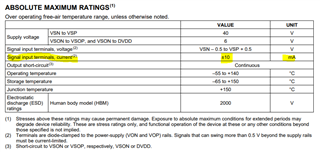
    In order to avoid damage in the future, it is highly recommended to set the current limit on your input voltage source to less than 10mA. This will help protect the input structure during the overvoltage condition. You may also consider populating R11 and R15 with 1kΩ resistors to further limit the current.

  • Hi Zach 

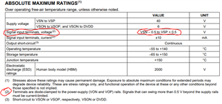
    Thank you for reply. I understand that also maximum signal voltage on pins IN+ and IN- should not exceed 0.5 V? 

    Kind regards 

    Rafał Kliza

  • Hi Rafal,

    I just wanted to let you know that Zach is out of the office at the moment, but he should get back to you within 2 business days. 

    Thank you for your patience,

    Alex Curtis

  • Hi Alex 

    Thank you for reply. No problem, I will wait :-). 

    Kind regards 

    Rafał

  • Hi Rafal,

    The absolute maximum voltage at the input terminals is defined by the supply voltage. See in the Abs max table, the voltage limits are set at VSN-0.5V and VSP+0.5V. Therefore for your supplies of +/-10V, input voltages higher than 10.5V or lower than -10.5V may cause damage to the device. See footnote 2, limiting the input current <10mA can help prevent damage during these overvoltage conditions.

    Regards,

    Zach