This thread has been locked.

If you have a related question, please click the "Ask a related question" button in the top right corner. The newly created question will be automatically linked to this question.

UCC2897A: Frequency Response Analysis of Peak current mode Active Clamp Forward Converter

Part Number: UCC2897A


Tool/software:

I am trying to reproduce the FRA response given following App notes(SLUA702)

"UCC2897A Peak Current Mode Active-Clamp Forward
Converter Small-Signal Modeling Design Consideration"

Now I tried to reproduce same small signal circuit in TINA but I am unable to reproduce the same bode plot given in app notes 

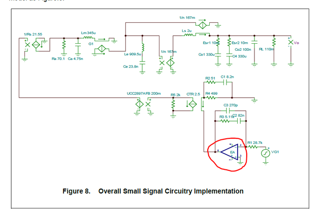
and when I tried to debug then found out error amplifier creating the difference 

Now given plot in datasheet is 
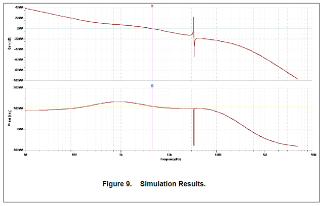
My plot is 

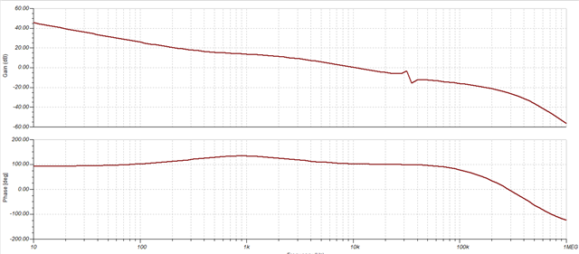
When I change the Error ampfier with different TI opamp it changes the gain crossover frequency .

How can I get the the EA used in the app notes ?

second question ,I would like to obtain input impedance of the converter ,how can I get that with this model.

  • Biswajit,

    -The E/A has a high frequency pole, which changes from different E/As. Using a different E/A will change the frequency of the high frequency pole and then the Gain and the Phase response will change.

    -I could not find the E/A Part number in the app note. Seems like it is not specified.

    -For the input impedance transfer function, you first need to derive the canonical model of the converter from input voltage small signal vi^ to output voltage small signal vo^ and make control small signal d^=0. Then, you can calculate the impedance seen at the input. To be honest, I have never done that in TINA, so I am not sure how to help with the simulation on that. I can guide you how to calaculate manually.

    Thank you

  • Many Thanks for your answer ,Its fine if nit simulation wise but if could guide me to calculate manually that would be really great ! Do you have any reference or could you guide guide me the steps how can I calculate manually?

  • Biwajit,

    I will be back to you at the end of the day today. Thank you for your patience.

  • Hi Manuel,

    Have you had a chance to look into the PCM Active Clamp Forward Converter Average Model?

  • Biswajt. Apologies for the late response. I am in time bank right now and it is national holiday in USA soon. I will reply back before Monda.

  • Have you had a chance to look into the PCM Active Clamp Forward Converter Average Model?

  • Biswajit,

    -Sorry for the delay. After doing some research on how to model the input impedance, I found the following resources:

    a. Please, see below the Canonical model of a buck converter (similar to forward).

    b. When calculating the input impedance, you can calculate it manually making d^=0 and then calculating the equivalent impedance of the inductor in series with the output cap and load resistor all reflected at the primary side.

    c. The transformer of the forward converter can be modeled adding the turn ratio on the transformer of the canonical model (n:M(D)). The magnetizing  inductance of the transformer Lm is generally much higher than secondary side inductance Lm>>Le, then it can be neglected.

    d. The question that comes up is: Active clamp forward has a closed loop and the canonical model seems to be open loop. If you think about it, when control small signal d^=0 (uc^ in the app note) in the equivalent circuit model shown in Fig. 6 of app note (see below) is zero, the components on the left side (Ra, Ca, Lm, Le, Ce) do not play a role in the final circuit mode, then it ends up just with the right side components (Ls, Co1, Co2 and Rl) which are the same components shown in the canonical model of the buck converter.

    e. I took the canonical model from the book Fundamentals of Power Electronics (Erickson and Maksimovic) Third Edition Section 7.4.3 Canonical Circuit Parameter Values for Some Common Converters, in case you want to read it more detaily.

    Thank you