This thread has been locked.

If you have a related question, please click the "Ask a related question" button in the top right corner. The newly created question will be automatically linked to this question.

INA219's: Power monitoring solution?

Anonymous
Anonymous
Other Parts Discussed in Thread: INA219, INA209, INA226, INA220, TPS65070

Hi,

I would like to ask a question on voltage / current / power monitoring on using INA219.

I am building a board using OMAP L138, and wonder how current and voltage can be precisely monitored on different power domains (split planes, etc.). I initially thought that some sophisticated lab instrument and wiring/plugging might be needed to measure them, however I later found a group of power-current monitors on a board I am referencing (SpectrumDigital EVMAM1808 schematics, sheet 36) that could possible solve the monitoring problem:


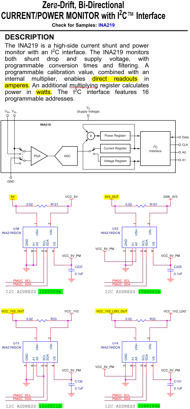
The INA219 current and power monitor has internal current, voltage and power registers, and seems is ideally suited for monitoring board power consumption. From the corresponding schematic page, different INA219's are connected to different power outputs of TPS65070 outputs:

Three step-down converters outputs

3V3_OUT

VCC_IO_3V3_1V8_OUT

VCC_1V2_OUT

Two LDO outputs

VCC_1V2_LDO_OUT

VCC_1V8_LDO_DOUT


And there are two other INA219's monitoring 5V and 1V2_RTC_OUT net current and power. Seven INA219's in total.

So it seems that with the equipment of these INA219's, from whom the processor can read current, voltage and power monitoring register results, the problem of precisely and delicately measuring board power consumption is largely solved. Even if individual devices cannot be measured separately, we at least still have knowledge of each different voltage domains. And there is no need, perhaps, to have sophisticated lab instrument in order to monitor the board power parameters.


So is this the purpose of the INA219's on that EVM board (SpectrumDigital EVMAM1808, see above)? And is this what INA219 is designed for?


Zheng

  • Hello Zheng,

    Yes, the INA219 is designed to monitor the voltage drop across a shunt resistor and a bus voltage.  Calibrating the device with your shunt resistance allows the device to calculate the load current and ultimately the power being dissipated by the load.  Many developers place current shunt monitors on the power rails of a design to understand the system impact of hardware/software changes during development.  Current shunt monitors, however, can be found in a plethora of additional end applications (e.g. consumer electronics, automobiles, industrial control, etc.).

    Care should be taken, however, in selecting the appropriate current shunt monitor.  Some of the parameters that need to be taken into account include the common-mode voltage, range of load current, shunt resistance, and accuracy.  The nature of the output is also a variable, though I will assume that you desire a digital-output.  If you are interested we also have analog voltage and current output devices.

    In your particular case I doubt that common-mode voltage range will be an issue for the power rails you're monitoring are likely to be much less than 26V.

    The range of load current affects 2 things.  First, the lightest load current will correspond to the worst-case accuracy.  This is because the shunt voltage (Iload*Rshunt) will be at a minimum.  The accuracy is essentially the ratio of the device's initial input offset voltage (this can be found in the datasheet) to the shunt voltage.  Depending on the grade and PGA setting, the INA219's initial input offset voltage can range from 50uV to 200uV maximum.  Secondly, you must ensure that the product of the maximum load current and the shunt resistance (the maximum shunt voltage) does not exceed the full-scale input voltage range of the device (assuming it is a digital-output device).  This is also provided in the datasheet.  The INA219 can accommodate full-scale ranges from +/-40mV to +/-320mV depending on the register settings.

    The shunt resistance should be selected based on the load current range and accuracy, as described above.  Another consideration is the power loss due to the shunt resistor (which may or may not be a consideration for you).  Also, one must also ensure that after the shunt voltage drop, the bus voltage remains within the tolerance of the circuitry it is powering.  

    We have a number of digital-output current shunt monitors in our portfolio...I suggest you take a look at them all to decide which is the best fit for your application.  They are the INA209, INA219, INA220, and INA226.  The INA226 is a recently released device that can perform the same basic functions (current, voltage, and power monitoring) but has an initial input offset voltage of only 10uV maximum.


  • Anonymous
    0 Anonymous in reply to Pete%20Semig

    Pete,

    Sorry for my late reply. I am still trying to under aspects of a PMIC (TPS65070), and would return to this thread some time later.

    I appreciate your detailed and helpful answer and I will study it.


    Zheng