This thread has been locked.

If you have a related question, please click the "Ask a related question" button in the top right corner. The newly created question will be automatically linked to this question.

Why THP210 is sensitive to the noise on Vs-

Part Number: THP210
Other Parts Discussed in Thread: TINA-TI

Tool/software:

Hi Team,


Please advise me on my question bellow.


Before I show you my questions, please let me explain the background of this question.

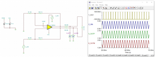
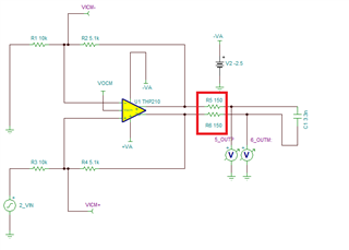
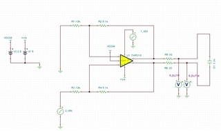
I am using THP210 with 5V single pole power and noticed that the

THP210 is sensitive to the noise on VS-, another word the GND.

So, I tried to duplicate this situation using TINA-TI and probably

observed the symptom.


Referring the simulation results, LMH210 output shows the unexpected noise

when the noise pulse on Vs- was coincide the low period of the source signal.


Question 1.  Do you think this is the expected result?

Question 2.  If so, can you let me know why LMH210 show this behavior?

Question 3.  Are there may workaround to fix this problem?


 THP210_in_tmp02.TSC

Mita

  • Hi Mita,

    Question 1.  Do you think this is the expected result?

    THP210 has excellent PSRR at 1kHz or even at 100kHz, so the injected noises or pulses should be significantly attenuated. 

    I think that the simulated issues you observed are likely to do with the 3.3nF capacitive load at the differential output. If the application is required to drive the 3.3nF capacitive load, you need to compensate the op amp and make sure that the op amp is stable. With the reduced capacitive load, I do not see issues. 

    Question 3.  Are there may workaround to fix this problem?

    You need to reduce the 3.3nF capacitive load or increase the Riso of 30Ω resistor. The differential op amp has to be stable. 

    If you have other questions, please let me know. 

    Best,

    Raymond

  • HI Mita,

    There are two separate issues with the circuit above.  One issue is related to the input common mode range (1), and the second problem is related to stability while driving the 3.3nF capacitive load (2).

    (1) The circuit above is also violating the input common-mode voltage range (VICM) of the THP210.  

    The VICM refers to the input common-mode voltage right at the input terminals of the THP210 Fully-Differential Amplifier.  The specification on pg 5 of the datasheet defines the VICM valid range as (V_VS-) + 1V <VICM < (V_VS+) - 1V; where this is the input common-mode voltage right at the input terminals of the THP210 need to be at least 1-V headroom away from both positive and negative supply rails.

    The circuit above is powered with a unipolar 5V supply, with the negative supply VS- = GND, and supporting a single-ended bipolar input signal of  ±5V centered at gnd.  The input common-mode voltage at the THP210 input terminals (VICM) is fluctuating between +2.50 and a voltage well below +1V, violating the input common-mode spec:

    A possible solution is to power the THP210 with bipolar +/- voltage supplies. See example with a positive supply of Vs+ = +5V and a negative supply of Vs- = -2.5V.  The input common-mode fluctuates between +0.8V and +2.5V, allowing more than 1V headroom above the negative supply (Vs-).

    (2) The THP210 circuit is unstable driving the 3.3nF capacitive load with a small isolation resistors of 30Ω. There are different possible methods to compensate the circuit. One simple solution is to increase the isolation resistors from 30Ω to 150Ω.  A detailed TINA-TI open-loop stability simulation analysis shows the circuit is stable with 46-degrees of phase margin when using 150Ω isolation resistors driving the 3.3nF capacitive load..

    Stability Analysis:

    Please let me know if you have questions.

    Thank you and Regards,

    Luis

  • Luis-san,

    Thank you for your advise.

    I will checg the cirucit following your advise.

    Mita