Tool/software:
I'm trying to read current of a motor driven with PWM using an H bridge (20kHz). I am using low side current sensing with a shunt and a TI INA180 amplifier. This will then feed the ADC of a microcontroller.
The amplifier output would be roughly a 20kHz square wave.
The reference input filter bandwidth is ~2.4MHz, the output filter bandwidth is ~1.6MHz. But the amplifier they use only has a bandwidth of 150kHz. I'm assuming TI knows a lot more about this than I do, but I was under the impression that the amplifier had to be faster than the filter or things would become unstable. Can someone help me understand this?
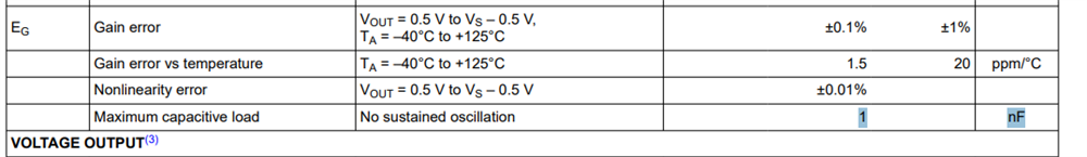
Also, the INA180 has a max output of 8mA. How is it capable of driving a 1nF cap through a 100ohm resistor?