This thread has been locked.

If you have a related question, please click the "Ask a related question" button in the top right corner. The newly created question will be automatically linked to this question.

OPA690: Electrical characteristics when supplying the OPA690 with single supply +10V

Part Number: OPA690
Other Parts Discussed in Thread: TINA-TI

Tool/software:

Dear TI support Team.

I intend to use the OPA690 with a single supply of +10V.

The application is 10MHz square signal to sine wave conversion.

The filtering is done with passive components: the OPA690 sees on its input a sine wave.

The OP690 is used in a non-inverting configuration with a gain of 2.25, and a capacitive-coupled 50Ohm load.

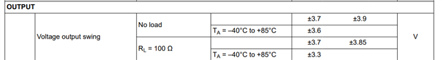
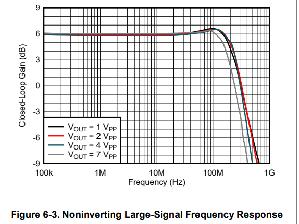
Can I use the electrical characteristics of the +/-5V tables and figures ?

Is there some limitations or special care (  headroom, bandwidth, stailibty...)  ?

Thank you for the supprt.

Nicolas.

  • Hello Nicolas,

      Here is a quick design for your requirements: (I have attached Tina-TI file to bottom of the reply as well).

         The low pass filter is a Sallen-key filter topology (since you mentioned non-inverting configuration) at a Butterworth response (Q factor of around 0.71) that gives the flattest pass-band. It can be adjusted to other filter types too depending on your key requirements. Note: I should have made it cut-off at around 12-15MHz instead, you can tune this depending on your cut-off requirements. 

       You are correct to take special care especially for a single supply configuration. The OPA690 will be able to handle a signal at 10MHz with a closed-loop gain of 2.25V/V as shown above.

       Note: Below is based on the OPA690IDBV. This device has different specifications for different package type. 

       For input and output headroom:

       Input range for 10V single supply will be typically around 1.15V to 8.85V

       Output range for 10V single supply will also be typically around 1.15V to 8.85V for 100Ohm load. This range will shrink a bit more with 50Ohm load. 

       If your total load is 50Ohms, you also have to watch out for output current, full-power bandwidth, and output claw curves depending on how high you want your output voltage. 

      The device is pretty fast with a high output current drive, and from the claw curves it doesn't change significantly with higher output currents. Therefore, I do not see an issue even at 8V with 50 ohm load for 10MHz signal. 

    OPA690 LPF Sallen-Key.TSC

    Thank you,

    Sima


  • Hello Sima

    Thank you for the reply.

    I'm actually not asking for a filter design proposal.

    I already did a design, run AC/transient (FFT) simulations and perform error calculations : I use two separate stages of passive LC filters.

    The results matches the requirements: there is a tight requirements on harmonics levels.

    But I need to be sure of OP690 electrical characteristics with a a single +10V supply : the datasheet only mention +/-5V and +5V usecases.

    From the screenshot you shared : are the electrical characteristics equivalent when using the OPA690 at +/-5V and +10V (considering a mid-point shift) ?

    Thank you.

  • Hello Nicolas,

      Yes, that is correct the electrical characteristics are equivalent when using the OPA690 at +/-5V and +10V and would just need to consider the mid-point shift for the recalculation. For best harmonic distortion performance, it is best to make sure the circuit is referenced to the mid-point of the supplies as well. 

    Thank you,

    Sima 

  • Hello Sima

    Thank you for confirming this.

    Regards,

    Nicolas