This thread has been locked.

If you have a related question, please click the "Ask a related question" button in the top right corner. The newly created question will be automatically linked to this question.

INA826: unexpected outcome from TINA simulation

Part Number: INA826


Tool/software:

Team,

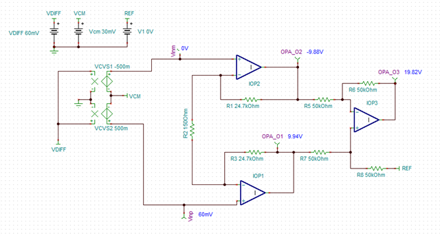
Posting on behalf of my customer.  They are using TINA to simulate the INA826 ( circuit attached along with .tsc file), but the output doesn’t match with the gain equation as shown in the datasheet.  Can you advise what the customer might be doing wrong?

  0880.circuit.docx

current_monitor1.TSC

Thanks,

Tom

  • Hey Tom,

    What's happening here is that they are violating their input common-mode range.

    From the datasheet, the operating input voltage range extends up to 1V below V+. Any higher, and the output will not be able to be linearly processed, and the gain equation will no longer hold true. 

    If the customer is looking to do a high-side current sense, they may be interested in a current sense amplifier, or they will need to drop some common-mode voltage before the shunt resistor. 

    Using the Analog Engineer's Calculator, we can see a couple things:

    1. The recommended maximum supply voltage is 36V
    2. when the common mode is at it's maximum value (>1V below V+) you have very little usable output swing. 

    Is there a specific reason the customer is looking at using the INA826 for a high-side current sense application?

    Best,
    Gerasimos

  • I was trying to see if the power supply has anything to do with the output, so I changed it to 40V, but in my design it is 36V, how can I get the gain to match with the equation. 

    Thanks,

    Chay

  • The calculator doesn't match with the Tina simulation as shown above images, which one use I use?

    Thanks.

  • Hello Chay,

    This is partially due to the input common-mode range. I made a mistake earlier, this is a low-side current sense, not a high-side current sense.

    Because of this, your common-mode voltage is near 0V

    At max current (3A) your CM voltage will be (60mV+0V)/2 or 30mV. Setting your CM to 30mV gives you a max output voltage of 1.46 volts.

    You are running into the output swing limitation of your device. If we construct the amplifier internals out of ideal components, you can see this clearly.

    For perfect devices in this condition, to get a linear output, your IN- amplifier would have to output -9.88V. This is not possible because your V- rail is 0V, and your internal op amps cannot swing below V-.

    There are multiple ways you can fix this.

    1. Change your supply rail to be 26/-10V, this will allow for the proper internal swing from rail with your specified common-mode voltage.
    2. Increase your input common-mode. However, to increase your input CM to a sufficient voltage to get a linear output, you would need to increase your input CM to ~10V, which would mean your shunt is 10V above GND, this shift may not be acceptable.

    Best,
    Gerasimos

  • can I use the same circuitry for high side current monitor?

  • Hey Chay,

    You will run into similar common-mode issues with the high side, as your input common-mode needs to be at least 1V below V+, which will not be the case for high-side current sensing. Instrumentation amplifiers are not well suited for shunt based current monitoring when operated on the same supply rails as the load. They work best if you can provide another power rail that will allow for more common-mode headroom for the internal amplifiers. When doing this, they can provide lower bias current when compared to current sense amplifiers, but there are many benefits to using a current-sense amplifier, like performance near and above the rail. Please see below for our portfolio of current sense amplifiers.

    https://www.ti.com/product-category/amplifiers/current-sense/products.html 

    Best,
    Gerasimos