This thread has been locked.

If you have a related question, please click the "Ask a related question" button in the top right corner. The newly created question will be automatically linked to this question.

Interferences on INA122

Other Parts Discussed in Thread: INA122

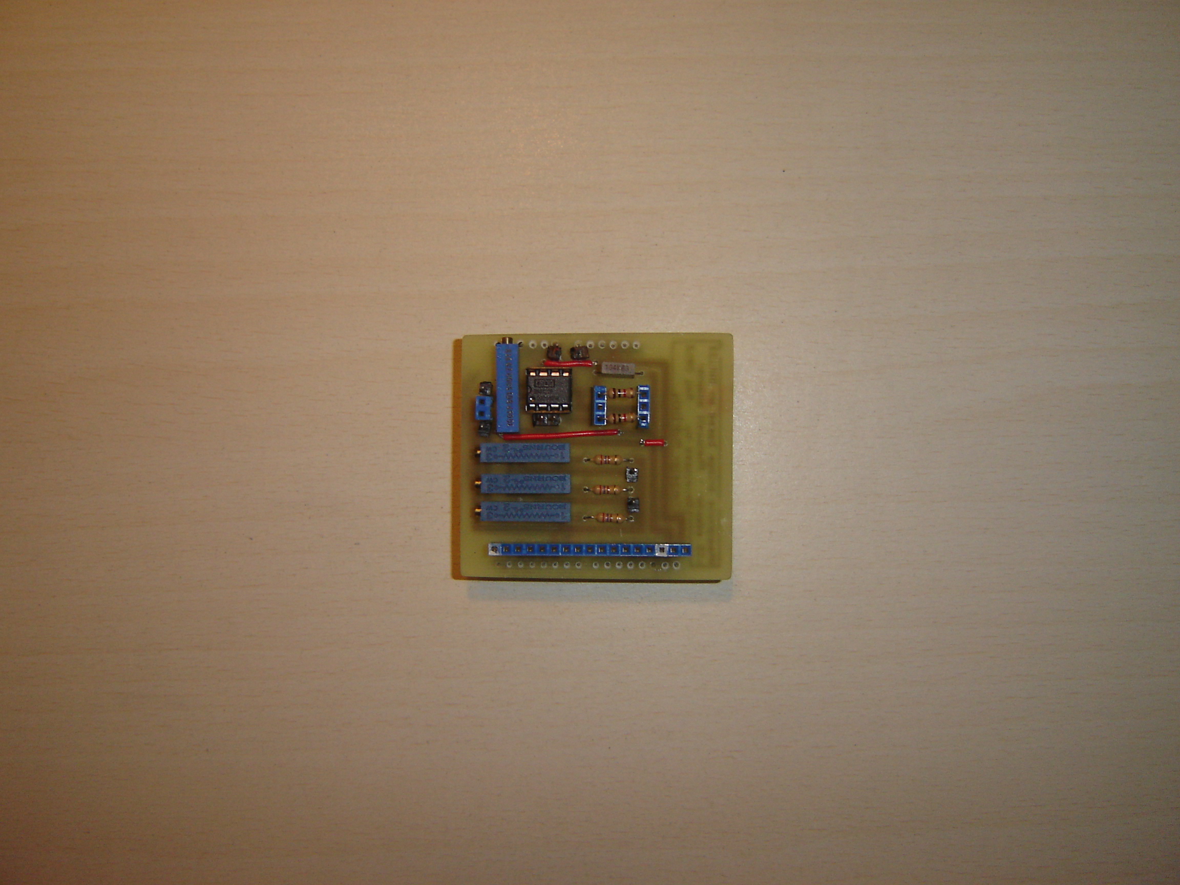
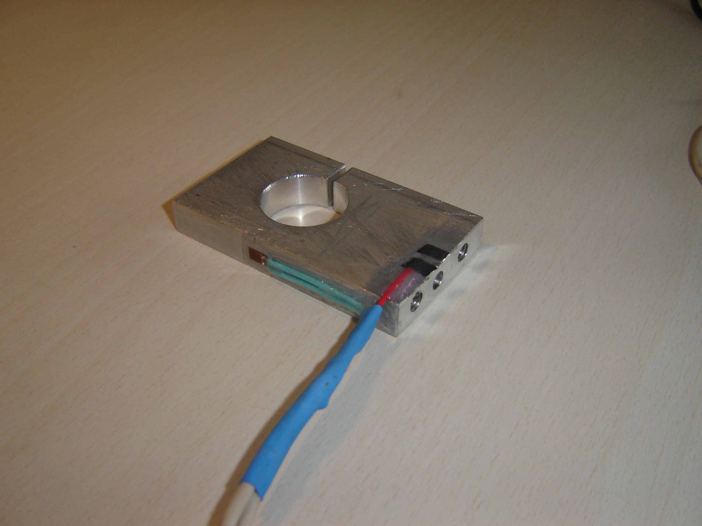
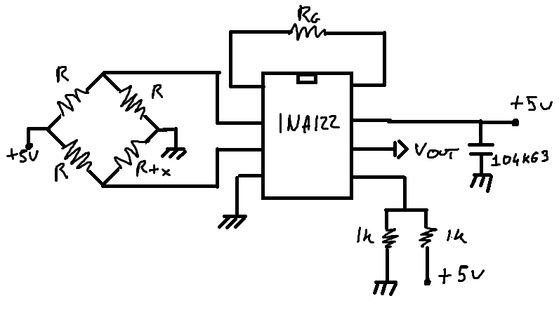
Hi, I have a problem with my loadcell and ina122 output. I've a wheatstone bridge connected to Vin+ and Vin-, Ref to 2.5v, and Rg is 500 Ohm. My output is too influenced by interferences on loadcell body. Seems there are no(or very low) interferences on circuit or on cable. Cable is shielded and the shield is connected to gnd and on loadcell body. If i touch loadcell body it stables and if i apply force it seem to work.

Here a video to better explain my problem:

http://www.videoweed.es/file/3p5c107xmjiar

Ty for your help.

  • Yaroslav,

    I will not be able to access the link to the video of your circuits behavior. Would it be possible for you to attach an oscilloscope screenshot to this thread to display the problem?

  • Here i've uploaded video on YouTube:

    The video above(in my house):

    http://www.youtube.com/watch?v=9_xijzOCyFE&feature=youtu.be

    Oscilloscope(At electronics lab):

    http://www.youtube.com/watch?v=DCwTh0cGBSo&feature=youtu.be

    Voltmeter(At electronics lab):

    http://www.youtube.com/watch?v=BBYLR_3kND0&feature=youtu.be

    As you see i have a lot of interferences near my house because of antennas.

    In the electronics lab i have an output more stable, but as you can see the output anyway oscillates too much(i set an output max amplification of 1Volt when i load max weight on loadcell). With cellphones off and others equiment off i have a variation of +/-0.35Volt on output depending if i'm near or 2m of distance from it. Anyway if i don't move it oscillates of +/-0.5|+/-0.10Volt. He become stable only when i touch loadcell body.

  • Yaroslav,

    It would appear that your INA122 is self-oscillating. That is to say, the AC waveform appearing at the output is not due to interference but rather is because the part is unstable. Would you please attach your schematic and if possible your board layout so I can provide some recommendations for your circuit?

    Thank you,

  • Yaroslav,

    There are a few issues that may be causing additional noise to appear in your circuit.To start, if this is a stability issue the capacitor you have placed on the output of the INA122 is most likely the culprit. Either remove this capacitor and re-test operation, or isolate it from the output of the INA122 with a resistor and retest the operation. If it is in-fact a noise issue, it may be coming from the Arduino board below. Is it possible to test the INA122 circuit without it connected to the Arduino board?

    Another issue is that a resistor divider is not a good way to bias the reference pin of the IC. These resistances are adding an additional 500 ohms in series with the on-chip precision resistors. For high common-mode rejection, the on-chip resistors of the part have to be very closely matched (they are trimmed with a laser during the fabrication process) and any resistance at the ref pin degrades the matching and reduces the ability of the part to reject noise. You should place an opamp configured for unity-gain (buffer) between this voltage divider and the ref pin.

    In terms of your layout, when laying out a pcb for an instrumentation amplifier remember that RG forms a loop on the circuit board with the IC, it is always good design practice to think of loops as antennas for noise. The range of frequencies for which these loops act as antennas is proportional to the loop area, thus you want to keep any loops as small as possible. It is hard to tell, but if you are using a potentiometer for RG this may also be acting as an antenna for noise, I would recommend you use a discrete resistor instead. Finally, I'm not able to see from the pictures, but if the cable connected to the load cell is not shielded you may want to consider adding a shield or switching to shielded cable. Long un-shielded cables are a common way for noise to enter a circuit.

    Circuits configured for high gains always require very good design practices to obtain low noise performance. By addressing the issues I name above you should see an improvement in the output noise of the circuit.