This thread has been locked.

If you have a related question, please click the "Ask a related question" button in the top right corner. The newly created question will be automatically linked to this question.

LM139 comperator

Guru 13485 points
Other Parts Discussed in Thread: LM139, LM139-N, LM339, LMC7211, LPV7215, LMC7221

I got the below question:

Problem: I would like to use comparator LM139 or similar
normal operation:
single supply 15V
input -   14.5V
input + 10v
output : open collector
unnormal operation:
no supply
input -   14.5V
input +  no voltage
output : open collector

How i can promise no damage to the device and no input latchup.
may be you have another device that can promise it
or there is  way to add a high resistor in series to the- input.

  • Hello Eli,

    We will never "promise" anything when it is operated outside datasheet specifications. No power supply is violating datasheet limits..so nothing is guaranteed.

    The LM139 does not have ESD clamps on any of the pins, so there is no input clamping to the supplies like newer devices. So current must be limited and external protection must be provided.

    A resistor in series with each input to limit the current into the pin is the first step. Since the internal devices and the body diodes themselves are providing any clamping action, I would limit the current to less than 1mA since the current is not going through a defined structure (like an ESD cell). This would require a minimum of 15K resistor (15V/1mA) in series with each input to limit the current.

    An external diode should also be applied from the input pin to the positive supply, so that the input pin is never more than a diode drop above the V+ pin - even un-powered. Note that this clamp could "lift" the power supply if it is lightly loaded.

    Another problem is that you are violating the input common mode range on the inverting input. The input common mode range is only up to 13.5V on a 15V supply.

    However, Note 3 (or note 6 and note 8 for LM139-N) states that the output will remian valid as long as one of the inputs remains within the common mode range. So as long as the inverting input stays below 13.5V, then the output will still be valid.

    So add the series resistors to the inputs, and a clamping diode between the input and V+, and you will be fine.

    Regards,

  •  

    Hello Paul

    I get some more information about my circuit and I would like if you can help me to select the right comarator.

    I use the comparator for interlock condition.

    I get power to the comparator for normal operation only after input - sense 1.5V 

    iF you can send me a direct email address I can send you my block diagram and then you can more to understand me

    ----------------------------------------------

    discription update


    single supply 3.3V or 5V

    INPUT -  between 0 and 1.5V

    INPUT +  1V (reference)

    output can be open collector (not must)

    unnormal operation

    no supply

     INPUT - 1.5V

    INPUT + no voltage


  • Hello Pesach,

    We like to keep the discussion on the community - so everyone can learn or contribute. You can inset an image into the post using the "Insert Image" icon in the text editor (8th icon on the bottom row from the right - with the red plus).

    Your statement "I get power to the comparator for normal operation only after input" concerns me. A comparator will not work without power - especially in an interlock circuit.

    Attach your diagram to your post so we can all see it.

    Regards,

  • Hi,

    Pesach have problems to reconnect to the E2E.

    See atached his feedvback/question

    1067.LM139 comperator.msg

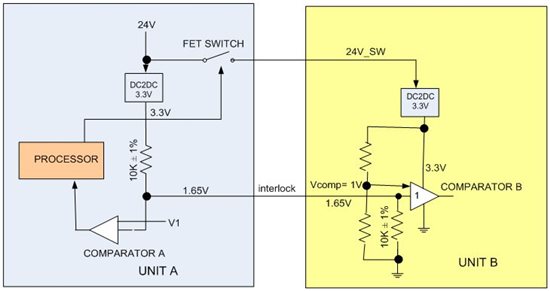
  • "Comparator A" could be a LM339 - but the input common mode range is too low and I would not feel comfortable using it in an "interlock" circuit while relying on the "one input in common mode range" exception. Same common mode range issue with Comparator B. To be "legal", comparator "A" needs to be a R-R input device. Comparator B does not need to be a R-R input device, but should have the common mode limit above 2V.

    "Comparator B" should be a CMOS input device. In order to prevent loading of the Interlock line when the power is off in unit B, there must be a large resistor in series with the input of the comparator.

    With the power off, most likely the input to the comparator will be clamped by the ESD diode to whatever the supply line randomly "floats" to. This could drag your "InterlocK" line to about ~1-2V - which could be a big a problem...

    To avoid this, you can place a large value resistor (100K to 1M) in series with the comparator B input (between the 10K and the input) to avoid dragging down the interlock line. Note that this series resistor would appear in parallel with the 10K resistor -so the 1.65V line may drop a little bit. Leave plenty of margin.

    A bipolar input device would have errors due to bias current going through such a large series resistor, so Comparator "B" should be a CMOS input device. It does not have to be a R-R input since the input will be between 0 and 1.65V.

    Since most of the comparators that operate at 3V are R-R input and CMOS, the choices are pretty much CMOS R-R input devices like the LPV7215, LMC7211/7215, LMC7221/7225, TLV340x/TLV370x and TLV349x devices. Take your pick...

    Hope this helps!

    Regards,

  • I have a question regarding the LM139.

    Is there a concern with using the open collector output to discharge a 3.3uF capacitor (charged to 5.1Vdc)? There is no "series" resistance between the 3.3uF capacitor and the LM139 output pin.

    The equivalent model (as shown on sheet 3 of the data sheet) would indicate that the output stage would go into Beta limit and thus the output voltage (Vsat) would rise as indicated on the figure shown sheet 8 of the data sheet.

    Lastly, I would assume that the "absolute maximum" rating of Isink (given as 16mA) would not result in device damage, but rather a condition of non saturation.

    I would appreciate any thoughts or comments, thank you in advance.

  • Ray, I would limit the current to 16 - 20 mA as the data sheet tells. If there is no current limiting resistor between the capacitor and the output, the internal resistance of the output transistor specifies the current.  I would never rely on the internal current limiter.

    Do you have a circuit example?

    If you need brute force discharge I would take an external fet/transistor which is capable to handle the discharge currents.

  • Marcellinus,

    It is a pretty simple circuit, and it is used in several places. I can't get the editor to paste, but a 3.3uF capacitor tied directly to the LM139 output with a 20.0k ohm pull-up to +5.1V. Normally the LM139 output is high, but on occasion it will go low and discharge the capacitor.

    Ray


  • Ray,

    Do you have failures with the LM139 who are discharging the capacitor? If not keep using them and trust the internal current limiter. Can you check the discharge time on a scope? If you do you can calculate the current which flows through the internal transistor at max/limit.

    Marcel