This thread has been locked.

If you have a related question, please click the "Ask a related question" button in the top right corner. The newly created question will be automatically linked to this question.

input and output inpedence of OP Amplifier opa333

Other Parts Discussed in Thread: OPA333

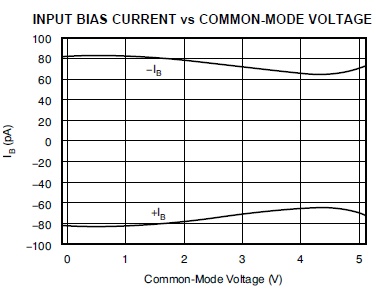
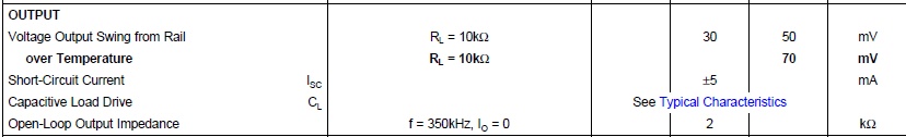
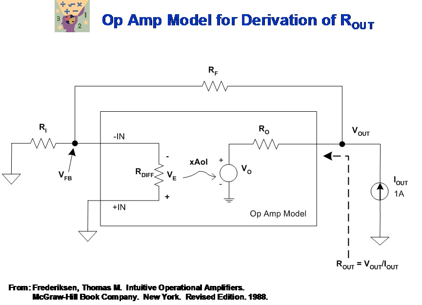
I am sorry I can not find input  and output inpedence of OP Amplifier opa333 on the datasheet, is there anybody who can tell me the really value of input  and output inpedence?

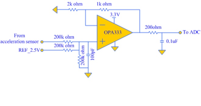
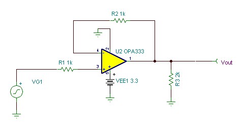
Is there any problen with the following circuit?

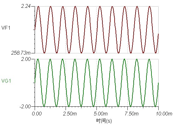
illustration: the + input port of opa333 is the signal between -2.0v and 2.0v, the output of opa333 is connected to 16 bits SAR ADC

  • Pan,

    The OPA333 differential and common-mode input capacitances are shown in the PDS to be 2pF and 4pF, respectively (see below).

    The common-mode input resistance may be calculated using the graph of Input Bias Current (IB) vs Common-Mode Voltage (see below).  Keep in mind, however, that the IB is not a constant current but rather an integrated current glitches coming from the switches of the chopping input differential pair.

    Rin = delta_Vcm/delta_IB = 5V/20pF = 2.5E11 ohm (250Gohm)

    The open-loop output impedance at unity gain bandwidth (most critical from stability point of view) is around 2kohm (see below).

    As far as the circuit itself goes, having large input resistors (200k) will result in amplification of the input current glitches coming from the chopping action of the input front-end.  Also, driving 0.1uF may be too much for OPA333 even with the help of 200ohm series output resistor - output may become unstable.

  • Marek Lis, thanks for answer.

    the following file  opa333.tsc is my simulate circuit, and the graph is the  simulate result , I can not find any Abnormal phenomenon. is there any problem with my simulation.

    3857.opa333.TSC

     as your analisis, having large input resistors (200k) will result in amplification of the input current glitches coming from the chopping action of the input front-end.

    while, how much the value of input resistors will be ok?

    you say that driving 0.1uF may be too much for OPA333,

    what is the value of capacity will be ok?

    the aim of circuit is designed to adjust the input signal range (-2.0v to 2.0v) to 0 ~2v ,then output to 16 bits SAR adc.

    do you have any better advice for me?


  • Pan,

    With R6 and C2 forming a low-pass filter with f~8kHz corner frequency at the OPA333 output, you would not be able to see ~10ns glitches glitches every 8us (125kHz clock rate) even if they were modeled but they are not; in order to speed up simulations time, the chopping current glitches are NOT included in the macro-model - otherwise, it would take hours to run simple transient response and days for more complex circuits.  The IB current spikes in the actual part are in uA range so 200k input resistor would result in few 100's mV voltage peaks but again ONLY if you had no low-pass filter at the output - with filter, there should be no problem as long as the large output capacitor does not cause op amp instability.

    OPA333 capacitive load  capability is represented by a graph of Small-Signal Overshoot vs Capacitive load where any overshoot in excess of 40% should be considered unstable caused by long-term process variations - by this criterion, OPA333 can directly (with no series output resistor) drive around 600pF (see graph below).  Of course, adding the output series resistor significantly improves capacitive load drive - the way to check whether the circuit is stable is to apply a small signal square waveform to its input (100mVpp) and determine the value of the output voltage overshoot - 40% or less should assure a stable circuit configuration.

    I ran the stability simulations outlines above which confirm that 200ohm series output resistor results in stable output response - actually, even 50ohm resistor should provide a stable operation (see below).

  • thanks , I have got your mean.

    But, I am still comfused that why the opa333 's output impedance is so big, nearly about 2k ohm. The output impedence of operate Amplifier I used before is very small, about several ohm. if the output imdepedance of opa333 is so big, Can it  still be used as follower which  ouputs to SAR ADC? as the below graph show.

    if VG1 input 1 to 2v signal,  can the point of VOUT  get 1 to 2v level signal? will the output impedance of opa333 will reduce the output signal?

  • Pan,

    There is a fundamental difference between the open-loop, Ro, and close-loop, Rout, output impedance. Since Ro represents output impedance inside the feedback loop, its effective close-loop value, Rout, as seen at the output of the op amp gets divided by the loop-gain - see attached short presentation.

    Rout = Ro / (1 +Aolβ) where Aol is open-loop gain and β a feedback factor

    Aolβ, loop gain, reduces Ro so that the output resistance of the op amp with feedback, Rout, will be much lower than Ro, for large values of Aolβ.

    Since the typical dc AOL of OPA333 is 130dB (3,160,000), therefore the effective close-loop output impedance for follower configuration would be:

     Rout = 2000ohm/(1 +3160000*1) =~0.6mohm at low frequency and will increase with decreasing Aol over frequency.

    Open vs Close Loop Zout.ppt
  • thanks for your Patient and detailed Answer,I have know Ro and Rout of OP AMP clear now.