This thread has been locked.

If you have a related question, please click the "Ask a related question" button in the top right corner. The newly created question will be automatically linked to this question.

constant AC current source

Other Parts Discussed in Thread: OPA548, OPA547, BUF634, OPA454, OPA452, TINA-TI, OPA551, OPA552, INA169

Hi,

I want to design a constant AC current source of current variable upto 200mA rms.

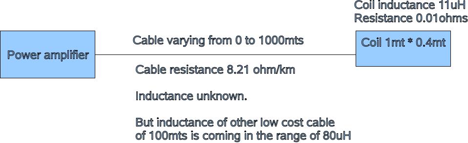
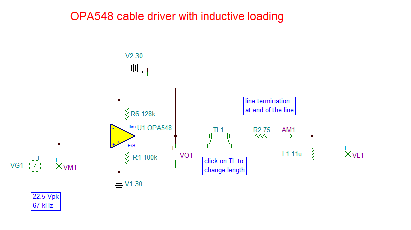
The frequency of the current source will be from 64KHz to 67KHz. The impedance range is 10ohm to 200ohm.

The load is a reactive load.

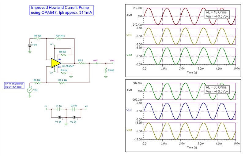
II used the Howland constant current source. But it doesnt worked out.

Can somebody tell me whether Ti has a readymade solution for this?

If not please help me if you have any idea.


Regards

Venkat

  • Venkat,

    A Howland current source is probably the best solution. Can you please provide a diagram of the circuit that you tried? Please provide details of power supply voltage and a description of how the circuit performance did not meet your expectations.

    Regards, Bruce.

  • The circuit works fine at 10Khz but is not working at 70Khz

    I am using OPA548. +/- 15V, 70Khz AC signal, 200mA current

    Is there any problem with the OPAMP.

    Is there any additional ckt to be provided.

  • Venkat,

    I'm sorry but we will need more information to provide more assistance. There are various reasons that your circuit may not be working as you would wish. First, we must know exactly what circuit you have tried... circuit values and load conditions. Please describe exactly what you mean by "is not working." How does the performance change as you change the frequency from 10kHz to 70kHz? Is it possible that changing nature of the load over this frequency range is changing circuit operation? What is the impedance of the load at 10kHz?  And at 70kHz?

    You may want to read this posting for suggestions on the type of information that may help us diagnose the problem.

    http://e2e.ti.com/blogs_/b/thesignal/archive/2012/07/23/clairvoyant-troubleshooting.aspx

    Regards, Bruce.

  • Hai Bruce,

    The circuit i am trying is the howland constant AC current source using OPA548

    The circuit I used is the same as below with changed values mentioned below

    .

    I kept U1 = OPA548

             R1 = R6 = 5.1K

              R2 =R7 = 39K

           R5 = open

    R4 = short

    R8 = 10ohm

    V+ = +24V

    V- = -24V

    VG1 = approx 400mV Pk- Pk 65Khz sine wave

    V3 = 0v

    when I am varying the load resistance from 10ohm to 100ohm the output current is varying, which is not desirable.

    But if the frequency of the input signal is changed to 6Khz the output current is not varying even if the load resistance is changed from 10 to 100ohms.

    why the current is not constant at higher frequencies.

    Is there any solution for this.

    Please reply me asap.

    Thanks in advance

    Venkat.

  • Venkat,

    I am traveling and have had only a short time to look at your circuit. I must say that I'm confused by the discrepancies between the circuit diagram and the text description. Furthermore, it is not clear whether you are only simulating your a circuit or measuring actual performance.

    In a quick check, it appears that the bandwidth of this circuit is approximately 10kHz and this is probably the cause of your problems. You can increase the bandwidth by changing R1, R6, R2, R7 all to 10k. This increases bandwidth to approximately 60KHz. You can further improve bandwidth by increasing R8, but with some loss in output voltage compliance range.

    Regards, Bruce.

  • Hai Bruce,

    The circuit diagram I posted is same as the circuit I practically tested but with different values of resistance and voltages.

    I mean to say see the circuit diagram for connections and for values see the text,

    I am measuring the actual performance

    How to calculate the bandwidth with the resistance values?

    If we increase the R8 then what will be the accuracy of change in o/p current with change in load resistance.

    My frequency range of operation is upto 70Khz. Is the 60Khz bandwidth sufficient for this.

  • Venkat,

    I've made some calculations of the output impedance of the improved Howland circuit as a function of frequency. The output impedance is a measure of the output current changes with output current. The DC output impedance of the Howland is dependent on resistor ratio matching. At high frequency, however, the output impedance is dominated by the bandwidth of the op amp.

    The output impedance, Ro, can be approximated by Ro =  n * R8 (GBP) / f

    n = the divider factor of the resistors = R1/(R1+R2) = R6/(R6+R7)

    GBP = gain-bandwidth product of the amplifier = 1MHz

    f is the operation frequency

    The basic problem with your circuit is the limited GBP of the OPA547. The resistor values I suggested provide a more favorable value for n. You may be able to increase R8 to a larger value but this will limit the output compliance voltage range due to the increased voltage drop.

    Given the power supply +/-24V and output current, I do not know of an easy choice for higher GBP amplifier.

    Regards, Bruce.

  • Hai Bruce,

    R u saying me to go for a higher GBP amplifier, If yes please suggest me an amplifier.

    I have a doubt that if I can decrease the   "n = the divider factor of the resistors = R1/(R1+R2) = R6/(R6+R7)" value to less than 1 can I overcome the GBP limitation

    Regards

    Venkat

  • Hi Venkat,

    Yes, you need a higher GBP amplifier. I do not know of a logical choice for your current output and voltage range. If you can operate at +/-15V, there are some other possible options. One possibility, for example, would be to use the BUF634 inside the feedback of wider bandwidth op amp. Otherwise, you are relegated to relatively small improvements with the existing circuit.

    There are other possible circuits using discrete transistors and an op amp but this can be tricky to design.

    If you can explain more about the nature of your requirements and application, I may be able to make other suggestions.

    Regards, Bruce

  • Hi Bruce,

    The main requirement is the current o/p of 200mA RMS and frequency of 67KHz.Frequency shouldn't vary by +/- 2Hz

    Actually my load is a rectangular coil of 1mt * 0.4mt with 2 turns. Its inductance is measured as 11uH.

    This coil is connected to the power amplifier by a cable which can vary from 0 to 1000mts.

    Resistance of the cable is 8.21 ohm / Km. The inducatnce of the cable is unknown. (does inductance present for a high cost wire or signalling wire)

    Then how to exactly design the power amplifier to drive the coil including the cable.

    Please reply me asap.

    Regards

    Venkat.

  • Venkat,

    You have a complicated situation because your cable length is a significant fraction of a wavelength. In some quick simulations I see that, even with a perfect current source driver, the current in the coil varies greatly as the cable length is changed. It may be possible to make an impedance compensation network on the coil end of the cable to match the coil impedance to the line impedance.

    This approach would require accurate information on the characteristics (impedance) of the cable and little or no variation in coil characteristics. If this is possible, then a voltage drive circuit may be suitable because the relationship of voltage drive to load current would be constant.

    Regards, Bruce.

  • Hi Bruce,

    Cable parameters are

    Inductance 0.6uH/meter, Capacitance 101pF/meter, resistance is 8.2milli ohm/meter.

    Then how can we design the impedance compensating network at the coil end.

    Please reply me asap.

    Regards

    Venkat

  • Venkat,

    Your cable appears to be approximately 75 ohm characteristic impedance.

    I must rely on a colleague for assistance with this problem as he has far more expertise with transmission lines. He is currently traveling but returns tomorrow. We should have some type of answer in a few days.

    Are you open to using a different amplifier? It may be necessary to use a different amplifier with a transformer to optimize the current/voltage ratio.

    Regards, Bruce.

  • Hi Bruce,

    We are open to use a different opamp.

    Can u please elaborate the way to design the amplifier.

    Regards

    Venkat

  • Hi Venkat,

    Bruce is traveling, but he and I are in discussion about your application. I will update you as soon as it looks like we have a doable solution.

    Regards, Thomas

    PA - Linear Applications Engineering


  • Hi Venkat,

    Bruce and I have put much time into finding a solution to your variable cable length/ inductive load application. Here is what we have decided upon:

    • The only way to accommodate the random length cable is to terminate it in its characteristic impedance. Doing so prevents any standing waves from being developed on the cable. That it turn prevents voltage maximas and minimas from being developed along the cable assuring the voltage at the termination will be close to that at the driving end.
    • The line has a characteristic impedance of approximately 75 Ohms based on the line constants you provided. Therefore, the end termination is set to 75 Ohms.
    • Fortunately, the 75 Ohm termination resistance is large compared to the +j4.63 Ohm reactance of the 11 uH inductor, at 67 kHz. The total load on the end of the cable is 75 + j4.63 Ohms which as can be seen is predominantly resistive. Although not a purely 75 Ohm load it comes close and the voltage at the load will vary little due to impedance mistermination.
    • An a.c. Improved Howland Current Pump was considered, but rejected due to all the additional complexities and requirements of your application. A standard voltage amplifier proved to be a more manageable and practical solution. It was determined that supplies greater than +/-24 V are required to assure adequate common-mode input voltage range; +/-30 V is recommended, but supply voltages a little lower in level should work.
    • The need for 200 mA RMS (282 mApk) current through the load requires (R + jX) requires approximately 22.5 Vpk at the input of the line. When I review the possible power operational amplifiers that can handle this task the OPA547 and OPA548 are the candidates. I selected the OPA548 because of its higher drive capability and low output impedance.
    • The OPA548 is configured in a unity gain buffer (+1 V/V) to maximize its bandwidth and to keep the closed-loop output impedance as low as possible across frequency. This is needed to keep the voltage and current as constant as possible with frequency.
    • An additional amplifier stage would be needed to raise the output of your 67 kHz source to the 22.5 Vpk level. Remember that its output must be able to swing 45 Vp-p and a similarly high voltage operational amplifier would be needed for this gain stage. OPA452 and OPA454 HV operational amplifiers are possible choices.
    • You can see the proposed circuit in the TINA schematic shown below. Also, I have attached my TINA-TI file for your evaluation.

    Regards, Thomas

    PA - Linear Applications Engineering

    OPA_xmsn_line_01.TSC
  • Hi Thomas,

    Thanks for the design.

    As I said previously that we want a load current of 200mA rms, now we want to change the current to 50mA rms only and the load inductance changed from 11uH to 90uH accordingly. For this condition(change in inductance made the impedance of the load to approx 35ohm) how we have to place the termination resistance. Is any capacitor required in series near the load to compensate the inductance or any other thing is required.

    Also we need to take the feedback from the cable whether the current is flowing or not in order to detect any short or open in the cable.

    Please give me some suggestions for the termination resistance as j38 ohm of 90uH inductance is comparable with 75ohm.

    Also let me know how to detect the short ciruit or open circuit in the cable.

    Regards

    Venkat Narayana

  • Hi Venkat,

    The more reactive the load impedance becomes the more difficult it will be to maintain the required current level through the inductor. However, the effect can be reduced by increasing the resistive portion of the load. But do note that the end of the cable still needs to be terminated in its characteristic impedance.

    Fortunately, you mention decreasing the current from 200 mA RMS, to 50 mA RMS. That decreases the amount of output swing the operational amplifier must develop to support the required output current. My suggestion is you add a series 75 Ohm back termination resistor at the output of the operational amplifier; this is in addition to the 75 Ohm termination resistor. I haven't had any opportunity to simulate this idea, but I do believe it will help reduce the variation in load current as the length is changed. Also, by reducing the output current demands opportunities to apply a lower output current operational amplifier are realized. The OPA551 and OPA552 have a 200 mA output current specification which will easily handle the 50 mA RMS requirement. They have the added benefit of higher bandwidth than the OPA548 and you can likely use your intended +/-24 V supplies. You may then be able to increase the gain of the stage from the originally recommended +1 V/V.

    I did try using a capacitor of the equal, but opposite reactance to cancel the inductor reactance in the OPA548 circuit I proposed. The simulations indicated that it did not have near the affects expected. You may want to try simulating the circuit with and without a capacitor in series with your 90 uH inductor and see if the performance is what you need.

    I would apply a power supply current shunt monitor to detect a current change should an open, or short occur in the output cable. This could be inserted in one of the power supply lines. Take a look at the INA169 high-side current shunt monitor data sheet. That should give you some ideas how to go about detecting a change in the current flowing through the cable. TI has a number of current shunt monitor products with different features that you could utilize.

    Regards, Thomas

    PA - Linear Applications Engineering


  • Hi Thomas,

    The problem with the feedback is even if the cable is cut i.e open circuit, current is flowing in the cable. By measuring the current in the power supply line it may be difficult to tell that there is opening in the cable because even if the cable is open also current is flowing in the cable, The open circuit current may be different for different lengths of cuts in the cable and may be equal to the actual current (without any cut or open in the cable) if the cable is cut near the load end.

    Please let me know if there are any other solutions for this.

    Regards

    Venkat

  • Hi Venkat,

    You should be able to detect and measure the voltage after the series back-termination resistor where it connects to the cable input. The voltage will be a specific level based on the load current and nearly constant for the matched condition - regardless of the cable length . If the cable is cut open, or shorted somewhere along its length, the matched line condition will be lost and standing waves will be created. Voltage maximums and minimums would be develop along the cable's length.

    The voltage change could be detected and used to trigger a cable fault alarm.

    Thomas

    PA - Linear Applications Engineering

  • Hi THomas,

    I have placed a series back termination resistance of 75ohms and also a load resistanace of 75ohms. 

    I am giving a voltage output of 8V RMS from the power amplifier.

    If there is no cut or short in the cable the voltage at the end of series back termination resistance is 4V rms.

    Suppose  iif the cable is cut at some point the voltage at the end of series back termination resistance should become 8V RMS and if the cable is short at some place the voltage should be approx zero.

    But this is not happening in my case. Voltage at the series back termination resistance behaviour is improper i.e at the open circuit condition at a distance of approx 500mts  the voltage at series back termination resistance is 1V and at short circuit condition the voltage is aprox 5V.

    But at the same time if the frequency of the signal is changed to 5Khz voltage maxima and voltage minima are coming correctly. But my frequency of operation is near 65Khz.

    Please suggest me a solution to how to take the feedback whether the load end is properly connected to the source.

    Regards

    Venkat

  • Venkat,

    Thomas is out of office today so I will provide an answer.

    As Thomas wrote in his previous post, a short circuit, or open circuit on the line will create standing waves and the voltage measurement after the back termination resistor  will be unreliable and variable, depending on distance to the open or short-circuit.

    The behavior will be different at 5kHz. It will require more than 10-times the cable length to create transmission-line-type effects at this frequency.

    Regards, Bruce.

  • Hi Bruce,

    R u saying that the feedback mechanism what Thomas said wont work?

    Then if that is the case please let me know if there are any other solutions for feedback mechanism.

    Pease reply me with a solution asap because it is an very very high priority task to be done.

    If it is possible to discuss orally or through any online chat please let me know as the communication through forum posts are getting very late.

    Regards

    Venkat.

  • Venkat,

    The voltage measurement at the line termination resistor can be used as a general indication of a possible problem. If this voltage is half the drive voltage, the line is probably okay. If the line voltage is significantly different than 1/2 the drive voltage, there is certain to be a problem of some type on the line. It is not possible to determine the nature of the fault (short or open).

    It may also be possible to have a condition where the voltage appears to be correct (half) but there is some type of problem on the line. This depends on the exact length of the line.

    Regards, Bruce.

  • Venkat,

    You may email me directly at thesignal@list.ti.com.

    Bruce

  • Bruce,

      In the case  of " It may also be possible to have a condition where the voltage appears to be correct (half) but there is some type of problem on the line. This depends on the exact length of the line " the feedback mechanism fails. Is there any other solution for this to detect the cable fault

    Regards

    Venkat

  • Venkat,

    I don't know of a way to detect this condition from the transmitting side.

    I'll offer another possibility--one that would significantly increase complexity. You might be able to make a circuit at the coil end that checked for a valid signal (or at least, a connection). It could periodically pulse the line (DC) or inject some burst of a different frequency to indicate an okay condition. If this signal is not detected on the transmitting side, you would know that there was a problem with the line.

    We are not prepared or equipped to assist in the development of this approach.

    Regards, Bruce.