This thread has been locked.

If you have a related question, please click the "Ask a related question" button in the top right corner. The newly created question will be automatically linked to this question.

Voltage-controlled current source INA105 boosted with OPA633 buffer

Other Parts Discussed in Thread: INA105, BUF634

Hello,

I'm trying to make a voltage-controlled current source to control a laser module (Flexpoint dot laser module 635nm, 4mW, DC 4.5-30V).

I want to provide a limited current (0-100mA) according to its modulation voltage (0-5V). 0V is maximum current, 5V is minimum current. 


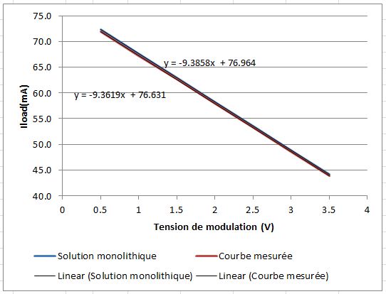
The graph shows the I-Vmodulation measured curve overlapping the therotical I-Vmodulation curve provided with INA105 and OPA633.

The INA105 with OPA633 works very well. I set V2 as the modulation voltage, R as 107Ohm and V1 as 8.19V but when I connect the laser module I get a totaly different rail that is much lower (40 to 33mA).

I don't understand why the laser module somehow can change the current source. 

Is there a way to 'isolate' the current source? Does this make sense?

I use TINA for simulation but I'm not sure there is a model for a laser module. If you know one or can offer an other equivalent model I'd be very interested.

Thanks

Charly

  • Charly,

    It appears that the voltage compliance range of this current source is not sufficient for your laser module. What is the voltage required on the laser module for the range of current you are driving? What power supply voltages are you using on the INA105 and BUF634? It may be possible to change the supply voltages on these devices to achieve proper operation.

    For a discussion of compliance range of current sources, see this:

    http://e2e.ti.com/blogs_/b/thesignal/archive/2012/04/03/current-sources-and-sinks-understanding-compliance-range.aspx

    Regards, Bruce.

  • Hi Bruce,

    Thank you for your answer. You were right the 'voltage compliance range of this current source is not sufficient for the laser module'

    The laser module can work with a fixed input voltage from 4.5 to 30V.

    I initially used +-12V on the INA105 and BUF633. After your post I increased the power supply voltages to +-16V on the INA105 and BUF633 and it worked much better though I can see a saturation for a modulation voltage below 0.5V (0V is max power-5V is OFF) and I wonder how I can get +-16V on the board.

    I think I can live with the limitation for now but I have other laser modules from the same manufacturer with different characteristics in terms of emitting wavelength and higher required voltages. I guess the circuit will then not be fitted for this kind of application.

    I tried to apply a negative voltage instead of the ground of the laser module but this didn't help. Is there a way to 'help' the INA105 and BUF633 to supply more voltage?

    Thank you for the links, I actually found the circuit with the  INA105 and BUF633 on the article 'Implementation and Applications of Current Sources and Current Receivers'

    Regards,

    Charly

  • Charly,

    I would expect that your trick of applying a negative voltage to the ground of the laser module should work. You  may want to carefully recheck your connections and try again. Another possibility is to use an unbalanced supply on the INA105 and BUF633 such as -5V, +25V. This would allow the module to be ground-referenced.

    BTW... I missed in your first post that you are using the OPA633 (which is a buffer) and referred to the BUF634 (an improved buffer). You picked up on the "BUF" prefix and called it the BUF633. There is no such part number so I just wanted to clear that confusion. The BUF634 is a more robust device that would work well in your circuits.

    Regards, Bruce.