This thread has been locked.

If you have a related question, please click the "Ask a related question" button in the top right corner. The newly created question will be automatically linked to this question.

Filter and Amplifier Circuit for Radar

Other Parts Discussed in Thread: OPA830, LMH6550

Dear Sir,

I wanted to use a filter amplifier circuit using op-amp which pass up to 30MHz frequency.

As this application is based on radar, there is going to be a lot EMI-EMC, could you please suggest some methods which will help in filtering EMI-EMC on the signal lines. I was going to common-mode chokes and pi-filters on the signal lines, will this be OK or do I have to add anything else?

I was intending to use OPA830. What op-amp do you suggest I use? The input range to the op-amp will 5Vp-p, I will bring it down to 2.5Vp-p with help of op-amp circuit itself. Also is this advisable?

Currently I am in the research stage of my project hence I am currently working on ideas and do not have any circuit to show as reference that I will be using.

Thanks Regards

Raquib Akolawala

  • If high EMC rejection is required and you are using differential signals in and out, maybe a differential amplifier like the LMH6550 would be a better choice.  Common mode chokes only work on differential signal lines.   EMC suppression can be quite challenging, it would be good to make sure you have a good idea of what the potential EMC spectrum looks like so you can focus the mitigation efforts.  If the EMC is outside your 30MHz bandwidth range then single ended signals with filters can be used.   

    Do you want to use an active filter or a passive filter? 

    If you decide to use an active filter you may want to have at least some passive filtering after the amplifier.  The amplifier needs to have closed loop bandwidth out to the upper range of the desired stop band.  Using a passive stage after the active filter will relax this requirement. 

  • Dear Sir,

    The inputs to the OP-AMP will be single-ended 0 to 2V pulse,500ns pulse width, Pulse repetition rate 100usec. (confirmed)

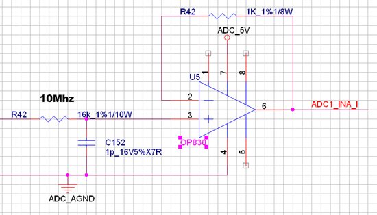
    The analog inputs line will have a T-filter followed by OPA830 (non-inverting mode 1st order filter) then a passive RC filter (10Mhz).

    I am currently testing the opamp circuit as given below.

    I haven't fully tested the circuit, but please let me know if the above configuration and opamp will be suitable for the purpose.

    Thanks Regards

    Raquib Akolawala