This thread has been locked.

If you have a related question, please click the "Ask a related question" button in the top right corner. The newly created question will be automatically linked to this question.

OP AMP Differentiate 1 mV

Other Parts Discussed in Thread: LM324, OPA735, OPA188, OPA2277, OPA277, LT1013, LM358

Dear Sir,

I am trying to find difference between two voltage sources using op amp. My application goal differentiate the voltage and give to ADC controller and it says what is the difference between two voltage.

I read using op amp as differentiators we can do it. but i need to get difference even it is 2 mV.

I am planning to use single supply for OP-Amp like LM324.

can i get such accurate result using op amp??

Or what else method will be good for this kind of application...

i am not good in op amp design kindly suggest a good design.

regards,

Nikhil

  • Nikhil,

    The term "differentiator" refers to a circuit that determines the time derivative of a time-varying input signal. These circuits are not what you want.

    You want a "difference amplifier" or an "instrumentation amplifier."  If you can provide more information on the type of signals you have, we can offer more complete advice. What is the source of the signals? Frequency range. Source impedance? Range of voltages with respect to ground?

    The LM324 is unlikely to provide sufficient accuracy for 1mV differential signal. The details you provide will allow us to determine better.

    Regards, Bruce.

  • Dear Sir,

    I want to find the difference between two voltage.

    The voltages are coming from one is direct from the voltage source  V1(SMPS) 12 VDC with respect to ground and next one is the output of the switch terminal V2.

    In simple i want to find the voltage difference ( Voltage Drop) between the main supply which is giving to switch V1 and output of the switch terminal when switch is in closed condition V2.

    Voltage Drop = V1 - V2.

    I hope the description gives a clear image.

    how can i design a good one with suitable  op-amp .

    can i use single supply for this. Because in  circuit there is no provision for dual power supply.

     Please help me.

    regards,

    nikhil

  • Nikhil,

    This may seem simple but, depending on requirements, can be a very difficult measurement. So I must ask more questions:

    It appears that you are trying to measure the quality of the switch contacts as the voltage should normally be very low. What is the purpose of the measurement? Do you intend to convert the measurement to a digital value? Do you want to alarm on a certain maximum value? Does the current in the switch always flow in the same direction? Is there a frequency response requirement for the measurement?  Is this a one-time measurement circuit or a high-volume production requirement?

    Answers to these questions could greatly change the complexity of the solution.

    Regards, Bruce.

  • Dear Sir,

    Here is the answer for your questions,

    1) What is the purpose of the measurement?

         To check how quality of switch. How much voltages it drop if we applied a certain voltage.  It has a limit for drop voltage. if drop is more than the limit the switch will be reject.

    2) Do you intend to convert the measurement to a digital value?

        I am doing this with the help of Microcontroller ADC (10 bit). If the microcontroller is not able to catch the small voltage drop such as 2mv, one more op-amp will come into the picture as amplifier.

    3) Do you want to alarm on a certain maximum value?

       Right now alarm is not needed. because the drop voltage passing to microcontroller and other calculation will do MC itself.

    4) Does the current in the switch always flow in the same direction?

        NO. it can be in any direction. depends how your going to place the switch. the Switch is a two terminal switch. it does not mention the polarity on switch.

    If the switch is placed one time on the testing equipment the direction of flow of voltage will be in one direction only unless it remove and replace.

    5) Is there a frequency response requirement for the measurement?

      No. You can clearly avoid this topic.

    6)Is this a one-time measurement circuit or a high-volume production requirement?

       It will be in high level volume production. And each test will take less than a minute. Is it make any difference between one time or production level measurement?

    I hope you got the clear image now.

    what all are the other  factors it depend.

    regards,

    Nikhil

  • Nikhil,

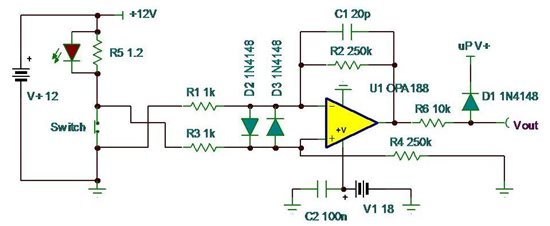
    It is more clear now that you are doing production testing of switches. A simple change in the measurement method will make this much easier. I show a circuit below that places the switch on the "low side" of the measurement circuit. This means that the measurement circuit no longer needs to measure a 1mV voltage in the presence of the large 12V voltage. R5 provides the test current.

    The circuit below shows the approach with suggested values for a G=1000 amplifier. A 1mV differential produces a 1V output.

    You must take care to make Kelvin probe contact to the switch contacts. This means that the measurement contacts must separately contact the switch terminals. They cannot share the contacts with the contacts that conduct the test current.

    The LM324 cannot be used for this circuit as its offset voltage is too high. You must use 1% resistors for R1,2,3,4.

    Regards, Bruce.

  • Dear Sir,

    Thank you for your support.

    By using this type circuit i can do my testing. But if the output is 1v for 1mv drop it will be critical for my controller if the drop becomes more than 5mv (Vdd of Mcu is 5V) .

    So i am going to change the gain from 1000 to 250. There for i can get 250mv for each drop. and i can check up to  19mv drop using this. Hope the changes in resistor R2 and R4 from 1M to 250K will give the required output without any other effect.

    Can you suggest any other OP AMP instead of OPA735. Because its maximum supply voltage is 13.2v. i need the 15 to 18 as maximum supply voltage.

    thank you for reminding about Kelvin probe contact.

    Regards,

    Nikhil

  • Nikhil,

    The OPA188 will provide similar performance and operates with up to 36V supply. I've shown an output clamp circuit to clamp the voltage to the a/d converter input to its supply voltage. This should prevent any serious overdrive of the input.

    Regards, Bruce

  • Sir,

    Thank you very much for your support. I am very much happy for your comments and co operation.

    It made a clear image in my testing circuit.

    Thanks again for sharing your valuable time.....

    Regards,

    Nikhil

  • Dear Sir,

    Can you suggest suitable op amps in DIP package for above function?.

    is it possible to replace High CMRR and low offset op-amps like OPA2277 for OPA188.?

    Does INA series can perform the same function?

    regards,

    nikhil

  • Nikhil,

    Your circuit requires an op amp that has a common-mode range that includes the V- power supply (ground in your case). This type of amplifier is generally called a "single supply" op amp. The OPA277 family does not meet this requirement. You would need an additional negative power supply such as -5V with this device. Suitable INA devices would have a similar requirement.

    You will find that very few modern op amp are available in DIP packages. Choices are becoming progressively more limited. Since your requirement is probably relatively low volume you may want to consider using an adapter such as described in this blog.

    http://e2e.ti.com/blogs_/archives/b/thesignal/archive/2012/12/17/breadboarding-with-micro-packages-ouch.aspx

    Regards,  Bruce.

  • sir,

    Thank you for blog.

    "Suitable INA devices would have a similar requirement."

    Would you don't mind can you explain how can i get a good one?

    Because i tried with OPA188 and it gets failed (Showing high difference if it connects at same source)  after some cycles.

    More over what is the important of R5 resistor in this circuit?  i did not used R5 in my circuit. is it the cause of failure?

    I hope my settings can replace with an instrumentation amplifiers and there are few precision single supply instrumentation amplifies.


    Regards,

    Nikhil

  • Nikhil,

    For various reasons, I think this circuit is the best choice for your application. Your requirement for single supply operation is the primary factor. I think the best solution is to solve the problems that you may have with the OPA188 circuit. If you are willing to add a negative power supply, I will make other suggestions.

    I show R5 in my circuit as one way to set the test current in the switch. How  do you set the test current in your circuit? Do you use a current source or current-limited power supply instead of the source I show as V+ (12V)?

    I believe that excessive voltage across the switch (defective switch or switch open) may cause failure. This might be prevented by adding back-to-back diodes across the switch to limit the voltage during switch-open conditions. I recommend power Schottkey type diodes that are capable of handling the test current.

    Please provide a complete circuit diagram of the circuit you are using. Include information on the power source that is used to create current in the switch.

    Regards, Bruce

  • Sir,

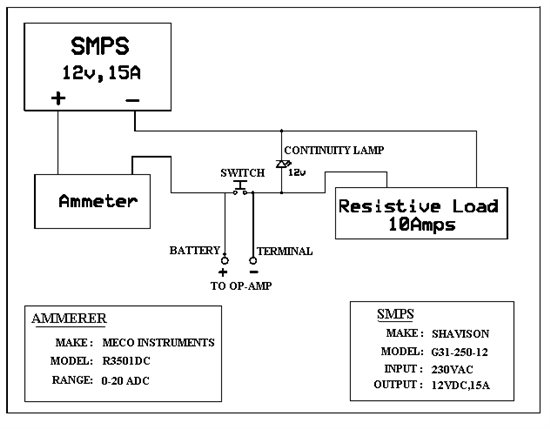
    I use SMPS of 12v,15Ampere power supply for testing.

    I took supply from this source for my MCU circuits with OP-AMP.

    To avoid excessive voltage to MCU i connected diode (1N4007) as shown in figure.Unless i am using SMPS there wont be changes in supply voltage / variation across the switch i think.

    Attached circuit diagram of Switch testing Unit.

    If adding dual supply source what changes will occur?

    Regards,

    Nikhil

  • Nikhil,

    You have not implemented the circuit as I have shown in my schematics. The switch must be connected to the negative (ground) side of the 12V power supply to achieve good accuracy. See my schematic below and connect as shown. R5 is the the resistor you call "resistive load."  The LED in my circuit is the same 12V indicator lamp that you are presently using.

    I have added D2 and D3 to further protect the op amp from damage.  Please ignore my previous comment regarding diodes placed across the switch as this would interfere with your continuity lamp function.

    Be sure to follow my previous recommendations on Kelvin probing of the switch voltage. Consider carefully the path that the high test current follows around the current loop on the left side. This current should not be allowed to flow near the ground connection of R5 or accuracy will be degraded.

    Regards, Bruce

  • Dear Sir,

    I agree my mistake what i did.

    what is the usage of D2 and D3 diodes.?

    There is an update regarding to voltage drop.

    Right now the design is to find the difference of 1mv drop. But in practical there won't be drop of 1mv. it will be in range of 100 to 300 mv. So while redesigning the circuit kindly consider milli volt drop range from 50mv to 999mv volt. Means the minimum measurable voltage drop should be 50mv. And please try to select DIP package Op-amp.

    Regards,

    Nikhil

  • Nikhil,

    D2 and D3 help protect the op amp when the switch is defective, switched to the off position or not inserted in the test fixture.

    100 mV to 300 mV seems like a rather high voltage to be present on a properly functioning switch. Your original purpose was to measure in the 1 mV range which seems more appropriate.

    I assume that the input voltage range of the a/d converter is approximately 0 to 3V. The new desired measurement range would require a gain of only 3 V/V. I suggest values of R1=R3=20k and R2=R4=60.4k (1% resistors). 

    OPA188 is still the best choice for U1. If you must use a DIP, LM324, LM358 or LT1013 might be sufficient. The output of these op amps, however, will not swing so close to ground so accurate measurement of switches with low voltage drop may be compromised. Adding a 4.7k resistor from the output of the op amp to ground may help mitigate this problem.

    Regards, Bruce

  • sir,

    Input voltage range of ADC is 0 to 5V. So i am setting gain 5 V /V by selecting  R1=R3=20k and R2=R4=100k.

    I am still choosing OPA188 as U1. But because of non- availability i requested for DIP package Op-amp.

    What will be accurate Voltage drop range ,if U1 replaces by DIP Op-amp  ? 

    The Both circuit is shown below, Using OPA188 and using DIP Op-amp. Check the design and suggest changes if any.

    Regards,

    Nikhil

  • Nikhil,

    Your first circuit is correct.

    Your second circuit should have R6 connected like the first circuit. An additional resistor, R7, should be connected from the output terminal of the op amp to ground.

    D2 and D3 are probably not required in the second circuit due to the different type of input circuitry in these op amps. Still, I recommend that you include them, in case you wish to change to the OPA188 using an adapter board.

    With R7 added to the second circuit, these op amps can probably swing to within 50 to 100 mV of ground on the output. This corresponds to a maximum of 20 mV on the switch. Also consider that the higher offset voltage of these op amps contributes directly as an error on the switch voltage measurement. The OPA188 reduces both of these sources of error.

    Regards, Bruce.

  • Sir,

    I corrected the second circuit as you mentioned. And in both R6 i am using 10K.

    According to your comment, i consider that OPA188 is suitable and the best OP-amp is for my application.

    I will check and revert to you back with testing result of new circuit using OPA188.

    thank you for the valuable support.

    Regards,

    Nikhil

  • Sir,


    The Provided circuit for testing the voltage drop for 2 terminal switch ( 1 Battery and 1 output).


    We would like to provide the same testing environment for multilateral switches using.
    For this we considering 4 terminal with One battery Rotary type Switch. But in this Each terminal is operating at different operating load. In our previous circuit we concluded that the operating load (10 Ampere) resistive load should provide at place of R5. But now we cannot follow the same logic for multinational switch due to the difference in operating load.

    How can i provide the testing environment for multinational switch (1 Battery and 4 Terminal Outputs)?

    Each terminal will switch ON at different position.

    regards,

    Nikhil

  • Nikhil,

    Please provide a diagram showing your switch and load arrangement.

    Regards, Bruce.

  • Sir,

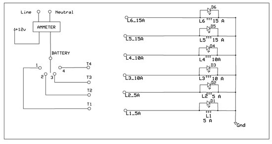
    Currently we are testing switch's continuity with load by operating manualy. The operating load will be different for each terminal. And each switches has different continuity pattern. So the operating load will be vary depends on the continuity. The operator decide and connect the terminal end to desired load. Some times the load will loop together if they want more load.

    Maximum operating load of switch of its one position is 50 Ampere.

    The switch testing specification as follows..

    Operating voltage : 12VDC

    Operating load : Depends on switch specification.

    Voltage drop  : 300mVolt. (Max)

    This time we can add dual power supply for better performance if you want.

    The testing setup as shown below.

    regards,

    Nikhil

  • Nikhil,

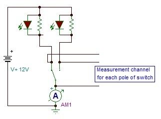
    I suggest that you configure the measurement with the switch on the "low side" at ground potential as shown below. Only two poles of the switch are shown. The measurement circuit is repeated for each pole of the switch and is Kelvin connected to the switch.

    Regards, Bruce.