I need a current generator of 1-2mA to supply an NTC. The power supply has to be 10 or 15 V. I wanted to use an XTR110, but it seems to me a little too big. Is not anything better for such a purpose ?
This thread has been locked.
If you have a related question, please click the "Ask a related question" button in the top right corner. The newly created question will be automatically linked to this question.
I need a current generator of 1-2mA to supply an NTC. The power supply has to be 10 or 15 V. I wanted to use an XTR110, but it seems to me a little too big. Is not anything better for such a purpose ?
Lucio,
There are many options to produce a constant current source. Some options for higher currents are shown in the TI Precision Designs documents (TIPD101, TIPD102, TIPD103, TIPD107). However, I will post a few simpler options here as well.
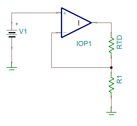
Option Number 1:
This circuit will produce a current through the RTD that is equal to V1/R1. It's downside is that the load will have to be floating.
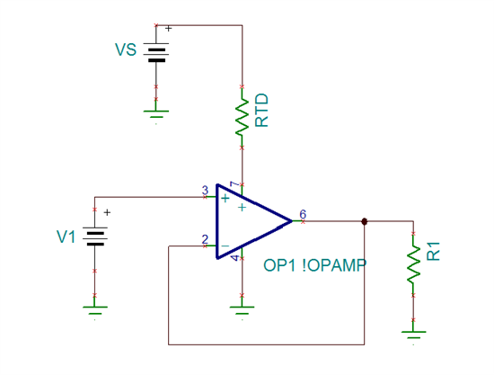
Option Number 2:
This circuit connects to the load as a low-side current sink. The current through the RTD is equal to V1/R1 + IQ, where IQ is the quiescent current of the Op Amp. The downsides of this circuit are that the quiescent current of the op amp can degrade the accuracy of the load current and that the power supply voltage must be high enough to accommodate the minimum supply voltage of the op amp as well as the voltage drop across the RTD. Also, one terminal of the RTD is at the power supply voltage, which may be too high for an ADC's input.
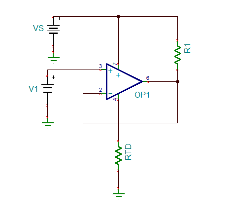
Option Number 3:
The last option allows for a grounded load, the current through the RTD will be (VS-V1)/R1 +IQ. With this current source be sure to consider the valid range of input voltages, assuming a rail to rail input op amp, the absolute lowest input voltage it could accept would be the RTD current times the RTD resistance. However, by carefully choosing the resistance values this may not be a problem.
John,
I mounted and tested the third option with an LMC6001 as Op Amp. Vs=10V. V1 =5 V, derived from VS with 2 resistors of 5 kOhm each. R1= 5kOhm. The goal was to get a 1mA current source. In fact the result was not satisfactory. With RTD ranging from 2 k to 6k2, the current varied from 0,88 to 2,6 mA. What was wrong ?
Lucio,
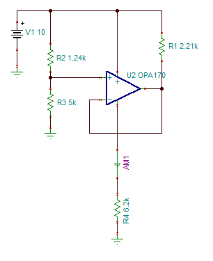
If the RTD resistance is 6.2kOhms, and you are attempting to source 1mA through it, it would have 6.2V across it. Thus, if your non-inverting input is at 5V, it is 1.2V below the negative power supply voltage of the op amp (6.2V) and outside the valid input range of the op amp. As I mentioned in my last post, the voltage at the non-inverting input must always be above the voltage across the load. Also, I would not recommend using the LMC6001 here as there are lower cost options with better common-mode rejection, power supply rejection, and quiescent current. Here is a design example using an OPA170. Here the voltage at the non-inverting input is chosen to be 8V, because it will stay within the valid input voltage range of the op amp for all load currents. Now the output resistor is chosen as: Iout - Iq = (10V - 8V) / R1 --> 1mA - 110uA = (10V - 8V)/ R1. R1 should be 2247.19 ohms and we use the 1% resistor value of 2.21 kOhms.
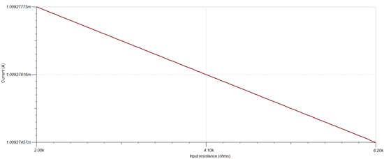
In Tina-TI I can now run a DC transfer characteristic sweep to see how the output current (measured by AM1 in the above image) changes as the RTD's resistance changes from 2k to 6.2k.
The output current changes from 1.00927775mA at 2k to 1.00927457mA at 6.2k which is a change of 31.8nA.