This thread has been locked.

If you have a related question, please click the "Ask a related question" button in the top right corner. The newly created question will be automatically linked to this question.

TIA with bootstrapping - Bandwidth Measurement method at bench

Other Parts Discussed in Thread: LMH6629, LMH6624

Hi everyone,

now I am designing a TIA with bootstrapping, mainly a normal shunt-shunt feedback TIA with another feedback loop of BJT. The photodiode is between the base and emitter of the transistor. The effective parasitic capacitance than could be largely reduced by the voltage follower(BJT).  The schematic is as below.

short explanations: C1 here to get an AC path, then the both ends of PD virtually unchanged, in this way the effective capacitance is lower.

TINA:0876.BFR540 BTA_LMH6629_post.TSC

in case the spice model is needed: BFR540 4265.BFR540_2.TSM

The problem of using a single high speed op amp, eg. LMH6629, though by some measures could be made stable with the great sacrifice of bandwidth. For a large PD(350pF), the 3db bandwidth still could not make up to 50MHz. (Simulation always can, be in reality not the same case, oscillation urges me to heavily compensate) That's why I introduced bootstrapping here.

For a simple shunt-shunt feedback TIA, I successfully used the way following to measure the bandwidth with VNA, the result somehow match the simulation, though with 20% discount.

http://e2e.ti.com/support/amplifiers/high_speed_amplifiers/f/10/p/293655/1025819.aspx#1025819.

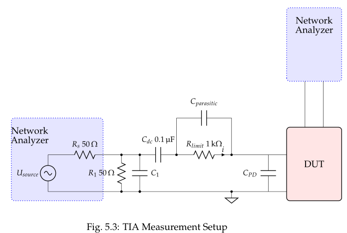
The problem is how to measure the real bandwidthin my circuit. One way that I thought about, is to replace the photodiode with the current source as below:

the resistor(6.2k) and capacitor(57p) are modified, for 6.2k*200f = 25ohm*57p

for the simulation is ok, however, i need to connect the VNA into this circuit, then the two grounds are not the same, meaning the ground of voltage generator and the output reference. I don't know how to solve this, are there other methods?  I tried to connect a signal generator and oscilloscope at the output, the output seems very unstable, i assume because of the float ground.

****************************************************************************

Question two about the stability.

when i use the single op amp, the stability could be achieved by some compensation or unity-gain stable amplifier. However, when i connect the opamp with the high speed bjt, the stability is hard to get. By inserting the resistor at base would help, but not always. Sometimes I need to put a finger somewhere (around base or emitter), then the oscillation would stop. Once removed, heavy oscillation returns. Esp. with large capacitance at the input.

I think, if my finger can overcome this with no bandwidth sacrifice(still low rise time), how to simulate the effect of putting a finger over the circuit? I try to parallel a small cap or resistor where my finger was, but it seems no help. Thanks. If the layout needed, i would post. I obeyed the shortest trace rule at my best.

So appreciate for the help, thanks!

BR,

Jason

  • Hello Jason,

    I do not have a lot of TIA experience, but maybe I can help with some of the measurements difficulties. 

    The VNA is AC coupled, so you won't need a hard DC reference point.  You should be able to AC couple the VNA input to the circuit and then use the VNA ground as the reference for your ground referenced amplifier output.

    A finger is a very low Q probe.  It is slightly capacitive, but it is very highly resistive.  The skin is usually around 100k Ohms, then internal tissues are water based on a ~4% saline solution and this is the capacitive effect.

    I have put the LMH6629 circuit into TINA and I can work with it and see if I can get more bandwidth.  Which gain setting are you using on the LMH6629?  It has a Av>=4 setting and an Av>= 10 setting.  You may want to use it in the Av>=4 setting which has more internal compensation, so it is more stable. 

    Regards,

    Loren

  • Hi Jason and Loren,

    Here are my thoughts:

    1. VNA connectivity to mimic a current source input: How about using an appropriate transformer / balun to convert the 50ohm input source on the primary to a differential / floating voltage on the secondary, with the 6.2kohm resistance you have chosen added to both secondary leads feeding the terminals across your dummy capacitance, C2? Is that a possibility?

    2. Stability with the BJT front end boot-strap: Here are the areas that I would explore to improve stability with the BJT in place:

    a) Small value ceramic (0.01uF) close-by cap to ground from Collector to ground, along with a larger one in parallel

    b) A ferrite bead on the LMH6629 non-inverting input lead. The bead should have significant impedance at the frequency of oscillation

    c) Loading the LMH6629 heavily (100ohm). Looks like you are already doing that.

    d) Replacing R10 with a 10k pot for an even larger resistance in series with C4. Forget the possible noise impact for the time being and adjust R10 higher to look for sensitivity. If successful, item "b" above can achieve the same stabilizing effect, without any noise penalty

    e) Change the LMH6629 COMP pin setting

    f) Ferrite bead in the emitter lead of T1 BJT


    Regards,

    Hooman 

  • Hi Hooman,

    1.for the measurement, yes, my professor also suggests me to use a balun to decouple the ground. And I did yesterday and today. I connect

    the secondary(2/1)

    --> 100nF(block DC) --> 1kohm(convert to current)-->  "so-called dummy cap"

    --> the secondary(2/2)

    However, the result seems not so good. I thought it was the problem of the power splitter that i was using.

    Then I used the same setup to measure the simple TIA, the result is almost the same as the one without the splitter. I think this could exclude the malfunction of splitter..

    I can not figure out the problem, I use a transformer (factor 0.5) in TINA, it also works prefect.

    2. stablility:

    2.a. I did put Caps near the collector

    2.f. I did try to put the bead at the base of bjt, it seems not much help, But i can combine the other measures that you suggest to try again.

    Now, I use LMH6624, which the GBW is around 2GHz, to replace LMH6629, and BFG25A/X(fT=5GHz) instead of BFR540(approx. 9Ghz). Together with other compensation methods, the oscillation somehow relieved, of course with the bandwidth sacrifice.

    There is still oscillation in the frequency(100Mhz, 900Mhz,1.2Ghz,) from the op amp. I put some more decounpling cap at the power ends, but no much help, I tried to put an Low pass filter at the output, no obvious improvement.

    and some boards happen to have 50Hz interference.

    br,

    Jason

  • Hi Loren,

    thanks for your reply, currently I am using the SOT23 package, so only Av>=10 could be used. 

    For the measurement, you should be aware that the other end of the current source is attached at the emitter of bipolar, so Hooman's method is theorectically the optimal one. However, as i said in the last reply, it didn't work at the moment.

    For the "finger effect"(let's name it like this), could be just use a large resistor, say 100k, and parallel with a small cap,say 0.2-0.5pF to mimik the finger? if not, how then?

    br,

    Jason

  • Hi Jason,

    The human body model for ESD is 100pF in series with 1500 Ohms.  In the absence of a spark the resistance would be higher, so maybe somewhere from 50k to 200k in series with 100pF might be a good model.   

    If you could build a probe and see which nodes are most sensitive it may help. 

    Loren

  • Hi Hooman,

    I have changed the connection of the test circuit.

    Before:

    just take one output of the splitter(say 1,and 1'), connect it to both end of the cap. the other output of the splitter left open.

    After:

    connect both outputs of the splitter(say 1&1',2&2'), take one of each(1,2) in series of dc block cap and 1kohm resistor to both end of the cap , and the rest(1',2') connect to ground of the board.

    theorectically both ways would do, but now it seems only the second way is right.

    But accidentally, the bjt broke last night after testing. I don't know if this is because of the float voltage?

    but since there is one end of the input to the ground, it should not be float to the bjt.

    -----------------

    br,

    Jason

  • Hi Jason,

    I tried to understand your description of the splitter to see if I can help, but unfortunately I cannot follow it! I think it'd be much better if you attach a schematic / picture.


    Regards,

    Hooman


  • Hi Hooman,

    sorry for the unclear words. Here are the schematics

    1.for the simple TIA

    2. Bootstrap amplifier with splitter(here is depicted as transformer)

    The circuits above work(at least from the result which makes sense)

    My curious question would be: when I connect in the way below, the result seems not right at all.

    These two setups all provide float voltage to the dummy cap, at least i think so. Or maybe there are some other reasons that i could not do it in this way.

    br,

    Jason

  • Hi Jason,

    To me, for what you are trying to do, only the 2nd arrangement you have shown makes sense. And only when the splitter you are using is a 180 deg. splitter (that is, the split ports are 180 deg. apart). Splitters also come in 0 deg. flavor (in-phase splitting) or 90 deg.

    Your 3rd arrangement is grounding one side of your photo-diode (lower connection of CPD cap) and is not any different than if you use the VNA port directly! This is not representative of the boot-strap setup you've shown (where the photo-diode is not grounded), so I would not use the splitter this way anyway to mimic a differential current input.

    Here are some180 deg. power splitters for reference:

    http://www.minicircuits.com/products/psc_pic_2_180.shtml

    Regards,

    Hooman

  • Hi Hooman,

    yes, the splitter is 180degree splitter from minicircuit - ZFSCJ-2-4+. The problem is the frequency range is 50-1000Mhz, the signal that i am measuring is around 20-50mhz. However, here the loss below 50mhz is not given in datasheet. the real measurement shows that it still makes sense in low frequencies.

    for the third arrangement, i did remove the ground of lower connection in the real setup (i forgot to erase it in the pic above)

    P.S. i figured out the reason, simple reason.... the grounds are connected inside the splitter.... 

    br

    Jason

  • Hi Jason,

    To recap, are you still waiting for some response from me (or others), or are you good-to-go now?


    Regards,

    Hooman

  • Hi Hooman, Loren,

    thanks for the valuable advice, i think for now the topic of measurement is answered. and for the stability, i changed to LMH6624,which is a slower op amp and also met the requirement, though not as good as LMH6629. I am still working on it.

    br,

    Jason