This thread has been locked.

If you have a related question, please click the "Ask a related question" button in the top right corner. The newly created question will be automatically linked to this question.

LM741 and INA114 - Sensitivity

Other Parts Discussed in Thread: LM741, INA114, OPA334, INA333, OPA734, REF200

Hello, 

This is my first post so I hope I ask the right questions! Both questions are for the LM741 and INA114:

1. Can they take in a signal of 0.2-0.5uV with 30-500Hz BW? 
2. If they can, will it distort it due to noise created from the chip itself? 

I've looked into the data sheets and I feel the noise density might be too much. However I  ran a simulation of it and it ran properly; just the simulation doesn't take into account external noise, power-line noise, etc. 

Cheers, 

Austin 

  • Hello Austin,

    You will need to calibrate out the offset voltage of any instrumentation amplifier or op amp that you select because your input signal is very small.  Our lowest offset instrumentation amplifier is the INA333, which has +/-(25 +75/G)uV of offset.  Our lowest offset voltage amplifiers are the OPA734/5 and OPA334/5 with 5uV of offset.

    Concerning bandwidth for the instrumentation amplifier you must first know your gain.  The INA114, for example, has a bandwidth of 1kHz at a gain of 1000V/V, which would meet your requirement.  As the gain decreases, the bandwidth increases.  Same holds true for the op amp...ensure that your gain bandwidth product does not exceed the data sheet specification. 

    Concerning noise, please see attached presentation. 

    I hope this helps!

    Instrumentation Amplifier Noise Analysis-clean.ppt
  • Hello Pete, 

    Thank you for the speedy reply,the noise ppt. was a very helpful resource as wel! But a few things I'd like to specific, then a couple more questions (my apologies): 


    1.My gain is limited to only 10uV/uV. It's a design parameter I can't go around I believe. 

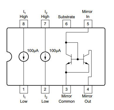
    2. I'd like the board ideally powered by +/- 5V supply, this is just one of the reasons why I went with INA114 for increased simplicity. INA114 is the 3 stage  in my circuit (1st is pre-amp, 2nd is high-pass filter, 3rd is diff amp, 4th is low pass) and is just doing differential voltage amplification (w/ mentioned gain of only 10). I have every op-amp with a null-offset voltage circuit in place; just slightly confused on the INA114's trimming setup, is it just a 10k pot set up as shown? Would those current sources be external chips, and what is 1/2 REF200 referring to?

    3. The thing that is turning me off from the OPA op-amp series is the single supply (although can get around it) and mostly their size. From what I saw on the data sheets they are not only small but surface-mount (unless I saw wrong, my apologies). I don't think I have the effective means to solder such small op-amps. This is another reason the LM741 was attractive for standard unity gain bandpass filter implementation.  

    Now kind of jumping back; at the end of this circuit (the low-pass) the signal is digitized with a 12-bit ADC and then is sample averaged (synchronizied averaging?) w/ N=200. Now if it's within the limits, won't the averaged digitized signal effectively have noise removed? Common noise caused from the circuit components such as the INA114 ?  


    If this is the case and synchronized averaging is applicable (hopefully) and considering the above points, would it be possible to achieve a minimum analog SNR of at least 2 ? 
     
    I realize I'm asking a lot and you've already helped, any sort of input is appreciated though, especially on the last point of averaging/SNR for this system! 

    Sincerely,

    Austin

  • Hello Austin,

    Yes, Figure 2 shows a 10kohm potentiometer and an external IC, the REF200.

    The REF200 is a dual current source as shown below (one IC, two current sources).  You would connect 1/2 of it (e.g. pins 1 and 8 to draw 100uA through one of the 100ohm resistors and the other half (pins 2 and 7) to the other 100 ohm resistor.  This will generate +/-10mV across the potentiometer which you can use to null the INA114's offset. 

    You are correct, most of our devices are surface mount.  Perhaps you could look into purchasing a smaller tip for your soldering iron.  In addition, there are a variety of lighted magnifying apparatuses that would help solder small devices.  Some attach to the table, some around your head.  Such a setup should be sufficient for SO-8 packages, which almost all of our op amps come in.

    While your averaging technique should reduce the noise and improve your SNR, you will likely get more improvement by gaining your signal as much as you can early in the signal chain using a low-noise amplifier.  So, make sure that first stage pre-amp is low-noise for it will dominate your SNR.  Furthermore, you may be interested in this blog post:

    http://e2e.ti.com/blogs_/archives/b/thesignal/archive/2013/01/21/put-gain-up-front-waxing-philosophical.aspx

    To be honest I can't state whether or not you'll ultimately obtain an SNR of 2 because there is a lot of missing information.  However, I believe that with the aforementioned suggestions and the presentation, you should be able to obtain a good estimate of your SNR.  Once you finish your calculations and simulations, feel free to post them for us to take a look at.

    I hope this helps!