This thread has been locked.

If you have a related question, please click the "Ask a related question" button in the top right corner. The newly created question will be automatically linked to this question.

OPA846 - the measurement of phase margin and gain margin

Other Parts Discussed in Thread: OPA846, TINA-TI

Hi All,

We'd like to ask the measurement of  phase margin and  gain margin on OPA846.

<Question>
Please refer to attached file.This is the result of phase and  gain simulation using OPA846.
2678.Phase margin and gain margin.pdf
OPA846 is trans impedance amplifers.

We don't know how to measure of phase margin and  gain margin using trans impedance amplifers.
If it is possible, please teach us them?(We appriciate you, if you write down to our attached file  the content to measure.)

We need your help.
Kind regards,

Hirotaka Matsumoto

  • Hello Hirotaka-san,

    For simulation purposes, I use the following technique to investigate stability of a Transimpedance Amplifier:

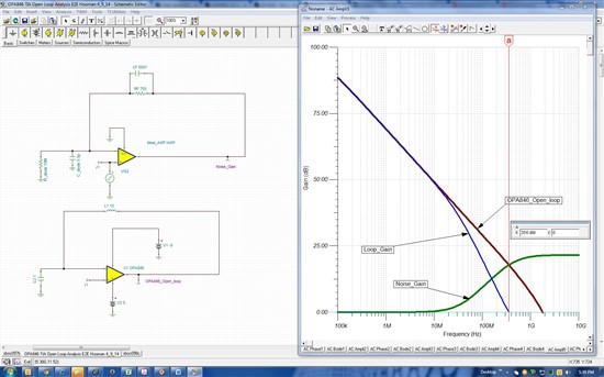
    1. Use a TINA-TI circuit which creates a Noise Gain function and extracts the OPA846 open loop gain / phase response simultaneously with one AC Analysis.

    -For the Noise Gain function, use an ideal amplifier with the feedback resistor, feedback compensation capacitor, photodiode capacitance, and photodiode eq. resistance, and any other components, all included.

    -For OPA846 open loop response, use a large inductor in the feedback and a large capacitor from the inverting input to ground (to provide DC feedback only)

    2. Run AC analysis simulation. Inside TINA-TI probe panel, click Edit, post-processor and create a function called Loop_Gain, as shown below, consisting of the ratio of open loop response and Noise Gain already determined by simulation.

    -Assign Loop_Gain as the "New Function name"

    -Click on it in "Available Curves" and then select Add>>

    _Click OK and the waveform gets added to the TINA-TI probe function and shows up

    3. Investigate the phase angle of the Loop_Gain function just created. The phase angle of Loop_Gain at the frequency where this Loop_Gain is at 0dB represents the circuit's phase margin.

    Here is the implementation of what I just described using the OPA846 and assuming an assumed photo diode capacitance of 15.5pF 5.5pF and 10Mohm impedance with CF set to 0.5pF (RF=750ohm). As you can see, with these conditions, Loop_Gain of 0dB corresponds to 356.8MHz by reading the cursor frequency:

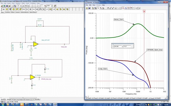
    Next, add the Loop_Gain to the phase plot. We will look at the Loop_Gain function phase angle (under AC Phase tab in TINA-TI probe) to read the phase margin at this same 356.8MHz.

    As you can see below, with these conditions, the phase margin is less than 8 degrees (=180 deg. - 172.7) and the circuit needs to be modified to improve phase margin (of course I'm just using a hypothetical example and your values / conditions will vary).

    Here is the TINA-TI circuit for the circuit I have shown above for your review and editing to match your conditions:

    3000.OPA846 TIA Open Loop Analysis E2E Hooman 4_9_14.TSC

    Regards,

    Hooman

  • Hi Hooman San,

    Thank you for your reply and your kindness!
    And then we applogize that we are late to reply for your excellent answer.

    We have a question the attached file 「3000.OPA846 TIA Open Loop Analysis E2E Hooman 4_9_14.TSC」.
    We choose the test AC_Transfier Characterisitc after that, the display shows "Line_edit : VP_OPA_Open_loop Unknown identifier".

    So, could you teach us what it means?

    We need your help.

    Kind regards,

    Hirotaka Matsumoto

  • Hi Hooman San,

    By changing the voltage Pin which is from "OPA846_Open_loop" to "VP_OPA846 _Open_loop",
    the message "Line_edit : VP_OPA_Open_loop Unknown identifier" disappears.

    However, in order to change values of CF, we choose "Select Control Object" on CF, set each values
    on "List 1pF, 3pF, 300fF" and then we acted "AC Transfer Characteristic".
    After that, "Line_edit : VP_OPA_Open_loop Unknown identifier" showed again.

    So, we'd like to sumilate with each values of CF.

    Kind regards,

    Hirotaka Matsumoto

  • Hello Hirotaka-san,

    Sorry I was out of office last week.

    If you step the value of CF 3 times, by selecting it as a control object as you have been trying to, then you need to delete the "Loop_Gain" function I had created and create three separate Loop_Gain functions by using the right Noise_Gain (1, 2, or 3) in its expression, as I've done below. I got the results shown below.

    BTW: I also get the same error message you have been getting if I don't do what I have noted above.

    Here is the modified TINA-TI file with CF stepped through the three values you had mentioned:

    4375.OPA846 TIA Open Loop Analysis E2E Hooman stepped 4_20_14.TSC

    Regards,

    Hooman