This thread has been locked.

If you have a related question, please click the "Ask a related question" button in the top right corner. The newly created question will be automatically linked to this question.

INA current sense problem

Other Parts Discussed in Thread: INA129, REF2925

Hi everyone,

I am using INA129 to sense the current from a sensor. The potential is scan from -1.2V to 1.2V (linear form from DAC) to the sensor and it produces the current in range of uA. The current is sense via a 100k resistor and then the INA will detect it with bias 2.5V. Here I set the gain  = 1.

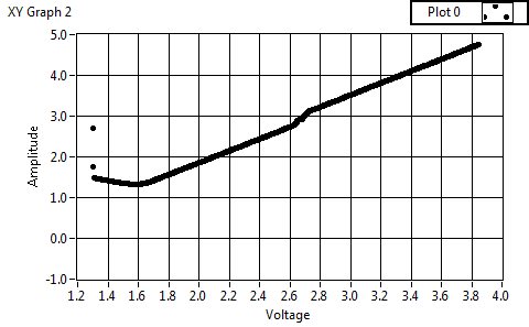
I test this part with a resistor at the place of the sensor so the current go through the resistor should be proportional to the potential, which means the output of INA should have the same form as the scan potential, a linear ramp (am I right?)

However, the output voltage read by ADC is not like that, it slightly changes above 0V (2.7V after biased).

I test ADC and it works fine. What could be causing the problem?

Thank you!

Quan

  • Hello Quan,

    The output swing depends on your input common-mode voltage, reference voltage, and gain. Please see the graph entitled "Input Common-Mode Range vs. Output Voltage" in the lower right corner of page 5 in the INA129 data sheet.

    In order to test this, I suggest grounding Ref and increasing your supplies to +/-15V. Please let us know the result.

    If that doesn't work, please try to determine if the error is related to the device or PCB. To do this, please use an o-scope or good digital multimeter to measure the voltage at the following pins: Vin+, Vin-, Vo, and Ref. Please be sure to measure at the pins of the device...not across R1 or any other location that may be more convenient.  

    I hope this helps.

  • Hi Pete, 

    Sorry for the late reply. I still tested the circuit with supplies +/- 5V but I grounded the Ref pin, one more thing I changed the gain of INA to 10, which I saw in datasheet it will give better common mode range vs output. 

    The results is right, it seems that the problem lies in the reference. I used REF2925 for reference voltage and it goes through no buffer. Is that okay for a stable voltage? 

    And one more thing I want to ask, I have read some documents about INA and they mentioned offset current. Could offset current contribute to the problem I am facing?

  • Hello,

    The output impedance of the REF2925 is very low, so I doubt this is causing any issues.

    The input offset current is +/-10nA (max). With a 100kohm resistor this will create a +/-1mV offset at the input. Given a gain of 10V/V that translates to +/-10mV at the output. The typical specification is 1nA, so I would expect to see +/-1mV at the output.

    I do not expect the input offset current to vary greatly with your load current, so if you're experiencing a gain error you should probably measure the input voltage at the pins of the device and compare it with the output voltage. Perhaps the PCB is causing a non-linearity.