This thread has been locked.

If you have a related question, please click the "Ask a related question" button in the top right corner. The newly created question will be automatically linked to this question.

INA170 Reference Voltage problem

Other Parts Discussed in Thread: INA170, INA3221

Hi

I've got a problem with my INA170 design.

Purpose: I want to measure a current of max +/- 100mA.

I chose the parts with the following values:

Rs = 1R

RL = 10k

Ros = 20k

Vref = 5V

V+ = 5V

With my calculation (equation (4) of the datasheet) Vout should be:

I = -100mA -> Vout = 1.5V

I = -50mA -> Vout = 2V

I = 0mA -> Vout = 2.5 V

I = +50mA -> Vout = 3V

I = +100mA -> Vout = 3.5V

Unfortunately in the reality I measure other values:

I = -47mA -> Vout = 1.52V

I = 0mA -> Vout = 0.124V

I = +47mA = Vout = 0.00V


I was doing the measurments with three differents INA170. With all I had the same result.

Can anybody help me and tell me what I'm doing wrong?

Thanks

  • Bernhard,

    Thanks for your question on the INA170.  Let me first point you to a little explanation I made for the INA3221.  You can ignore the digital interface parts but the analog portions are applicable as they discuss measuring small currents.

    http://e2e.ti.com/support/amplifiers/current-shunt-monitors/f/931/p/379461/1336207.aspx

    I'll dig a little deeper into your question and data shortly.

    Best regards,

    Jason Bridgmon

  • Bernhard,


    One thing I noticed is that you are looking for current measurements with low Vsense voltages.  According to the plot TOTAL OUTPUT ERROR vs VIN on page 4 of the data sheet, you can see that as Vsense goes below about 15mV, the error really increases significantly.  This could be indicative of what you are seeing with 0mA current, though without a little more information I can't say for sure.  Could you perhaps share your circuit diagram with me?  You may email it to bridgmon_jason@ti.com if you would like to keep it private.

    What is the common mode of your application, and is it stable as the current changes?  I'm referring to the Vp in figure 1 of the data sheet.

    Thank you,

    Jason Bridgmon

  • Bernhard,

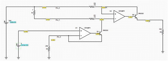
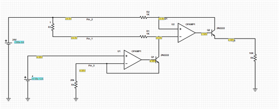
    I did a TINA simulation and tried your values in it and found that the results you measure do look similar to the results of the simulation.  Also, I found that if you use Vref of 4V, you can get an output that swings nicely between 1V and 3V.  A resistor divider of 1k/4k off the 5V Vsupply worked nicely and only consumes 1 extra mA from the supply.  You could likely use 10k/40k without much trouble if you need even lower current.

    Jason Bridgmon

  • Jason

    Thank you for your help. With Vref = 4V it works!

    I had done a simulation too and found the reason:

    With Vref = 5V, the Output of the OPAMP1 = 5.59V. In reality this isn't possible cased of the 5V supply for the Opamps...

    With Vref = 4V its better...

    Best regards
    Bernhard