My application involves controlling fans to keep device temps within specs. I need to monitor high side current in this application, ie, the current powering the fans. Current span is 10mA to 500mA. Vout will feed directly ADC of CMOS uP.
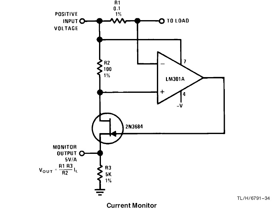
I've been simulating this circuit below, as per snoa620, AN-32 Fet circuit applications, pg 12:
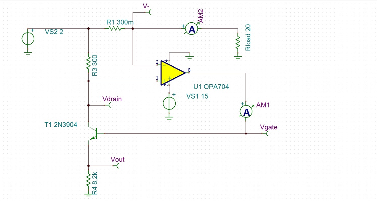
Previous inaccuracies made me switch op amp to OPA704 (which will be OPA705 in real circuit, but there is no model for 705).
Also used 2N3904 replacing JFET 2n3684, since I found no JFET model in TINA and no easy model for 2n3684 around. R1 and R3 have been set to resistor values that I already have. Relationship of 1/1000 was kept intact. R4 = 8k2 instead of 5k gives about 4.1V for Vout when Iload is 500mA, which is nice.
TINA circuit attached. high side.TSC
Power source for fans (VS2 above) is an LM317 with modified feedback network, so I can apply a wide input voltage range.
I have compiled a sweep list for different VS2 values and found:
| Vin | Iload | Vout | V/A |
| 12 | 0,591 | 4,891 | 8,274 |
| 10 | 0,493 | 4,080 | 8,282 |
| 8 | 0,394 | 3,268 | 8,293 |
| 6 | 0,296 | 2,456 | 8,309 |
| 4 | 0,197 | 3,930 | 19,944 |
| 2 | 0,099 | 0,828 | 8,407 |
For Vin (=VS2) = 4V and values around, circuit goes crazy. Vout is much higher than expected. It goes back to normal when Vin = 2V or lower.
Same thing happened for other sensitivities, ie, other values of R4, although at different values of Vin.
Why is this circuit behaving like this near Vin = 4V???
Side question1: why circuit overall sensitivity (V/A in above list) slightly increases when Iload decreases??
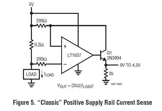
Side question2: is the only difference from this circuit shown to balanced circuit below the bias current compensation or is there any other reason for the 200ohm resistor at op amp V- below??
Thank you.


