This thread has been locked.

If you have a related question, please click the "Ask a related question" button in the top right corner. The newly created question will be automatically linked to this question.

INA170 powered from -5v and +5v from a charge pump(TCM829), output offset voltage not what I calculated

Other Parts Discussed in Thread: INA170, TINA-TI

Hi All,

I am having some trouble with setting the offset voltage for the INA170. this is what i have done...

So as stated the V+ pin is connected to +5v. This is also the input for the charge pump.

the ground for the INA170 is -5v from the output of the charge pump. I have done this as I want the output voltage from the ina170 to be between -5v and +5v so i can read it with the range another tool can read over with the best resolution possible.

the vref is set to the ground of the system (ground of the charge pump) 0v that is

Rl and Ros are both 50k to give a gain of 50. and an offset voltage of (Vref / Ros) * Rl which should give an offset of 0v.

I see an output voltage from the INA170 of around -5 v when no current is flowing. I was expecting to see 0V (Vref)

------------------------------------------------------------

another way to think about this...

consider the -5v as ground from the charge pump

then the vref is +5v and the power to the INA170 is +10v

using this i should get a voltage offset of (vref / Ros) * Rl or (5/50) * 50 = +5v, again half way between ground and the ina170 power voltage. but i see it as close to ground(in this example)

---------------------------------------------------------------

Any help you can offer would be greatly appreciated.

Many thanks

Liam

  • Liam,

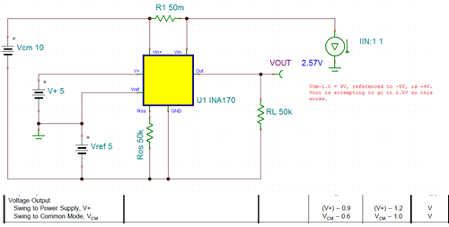
    I put your circuit into TINA-TI and simulated it, and I get the same results you do. I have a question, what common mode voltage are you using (referenced to charge pump ground)?

    Just to be sure I have the right idea, you are attempting to get a bidirectional current sense that provides an output between -5V and +5V?


    A follow-on question, have you chosen a shunt resistor value yet and how much current do you expect run through it? I'm wondering if a different current shunt monitor might be better suited for this application, which is why I'm asking.

    Let me know and I'll put together a circuit that gives you an output more to your liking.

    Thanks!
    Jason Bridgmon
  • Liam,

    By raising the Common Mode voltage to something like 10V, I believe your circuit may work.  There is a line in the spec table that explains how far the output can reach with respect to the common mode, and I believe you may be clipping your output with a low common mode.  In the TINA-TI simulation, this worked.  Screenshot below, and Sim file attached.

    INA170 bipolar.TSC

    I hope this helps.

    Best regards,

    Jason Bridgmon

  • Hi Jason,

    Thanks for the quick response. I have had a look at the simulation you made and that is almost what I had.
    in my design the current being measured is on a separate system, with no shared ground. in the simulation this would be like having the negative of the Vcm supply connect to the constant current load (instead of the ground). this didn't work for me and i get a -5v output as i did in the actual circuit. I tried connecting the negative of the Vcm to the ground of the charge pump (ground/vref in the simulation) and the output at 0.01 amp current made an output of around 50mv which is close enough to zero for me to think that it was working. I would have liked to connect the ground of the system I am measuring to the ground of the INA170 as in your simulation however this is also powering the charge pump and so it would be the same as connecting the -5 to ground( a dead short?). I have simulated and tested with the ground of the system i am measuring connected to the charge pump ground(vref in the simulation) and it seems to work on the simulation however i get some strange results in the actual circuit as follows...

    when I put current through the shunt in the positive direction(as in the simulation) it works and the voltage on the output goes up., but when i put current through in the negative direction first the voltage goes up(until around an amp) then it goes down as it should. I am not sure what is causing this. another observation is that when no current is flowing i get a slightly negative output (around -0.2v ) and when i put the negative current through the shunt it first increases the voltage to around 0v then it goes down as it should for current in this direction.

    As far as the shunt resistance and maximum current etc this is what i have done...
    first i measured the shunt voltage with 2A running through it and got 0.007v (i don't have the spec for the shunt so had to measure its properties) from this i know that it is 0.0035 ohms

    i calculated the maximum voltage for 30 amps as 0.0035*30 to get 0.105v with a gain of 50 this is around 5v so 5 up and down i needed 10v

    Thanks again for the help

    Liam
  • Liam,

    Sounds good. Thanks for letting me know it worked out!
    Jason
  • Hi Jason,

    im nearly there but I am not out of the woods yet! The issue I am still having is that when I increase the current in the negative direction the output first goes up until it reaches around 1amp, only then the voltage goes down. I have just thought of something though... in my circuit i have not got the shunt connected to the high side of the system i am measuring it is between ground and the component. can these shunt monitors work on the low side?

    Many thanks

    Liam
  • Liam,

    The common mode range is from +2.7V to +60V, so you'll have to bias it above the GND line (which in this case is at -5V) to make measurements.

    Best regards,

    Jason Bridgmon