This thread has been locked.

If you have a related question, please click the "Ask a related question" button in the top right corner. The newly created question will be automatically linked to this question.

Opa355 RfI

Other Parts Discussed in Thread: OPA355, OPA2355, LMV861, LMV881

Hi I have been using Opa355 in my current products with good success. (Shipping in several K units). It is used in a Tia with 8M gain at 1MHz signal.

I recently started a new design and this design uses wifi. With the new design, I see an in band Rfi rectification due to wifi. Design is ac coupled simple transimpedance amplifier. I amplify in two stages. 400k in first stage and 20 in second. I use 1.8v as reference voltage and opamp is using 4v supply. I have very little noise and excellent signal performance when wifi is turned off.

The only issue is really Rfi rectification. When wifi is transmitting I see a DC shift in first and second stage output. Due to high gain even a small shift result in nasty output swings. The design uses high quality bypass caps on supplies, 15v bias on the pd and 1.8v reference ground. (I still see the issue when I remove the pd from the circuit so it is clearly picked up by either my ground or opamp)

- I have added 100pf to the reference pin (+) which helped but added noise.

- I tried shielding using copper tape but I cannot get reliable results. Looks like I need to build something more sophisticated but not so sure it will work.

- spin another board with other protections etc.

- use another opamp with better Rfi tolerance is the last resort I really like this opamp and don't want to change but I don't know how to move forward.

Assuming I respin the board what precautions I can take? Appreciate inputs. Thx. Kt

  • Hi KT,
    Is the shift a constant DC level when the wifi transmitting? If so AC coupling between your TIA and 2nd stage amplifier will help to deal with this issue. The first job in attacking EMI/RFI issues is identifying antennas on the PCB. PCB traces may start to exhibit antenna-like behavior in lengths as small as 1/10th the wavelength. Assuming the wifi signal is at 2.4GHz, this would be 12.5mm (~1/2 inch). The most critical traces in your circuit are going to be those leading to the op amp inputs. Be sure that the OPA355 configured as a transimpedance amplifier is very close to the photodiode on the pcb and that the second amplifier is very close to the TIA. The feedback resistors on both of these amplifiers should be as close to the op amp as possible to reduce the loop area of the feedback path. Furthermore, both of these amplifiers (and any high-gain amplifier circuit) should be as far from the wifi antenna as possible on the PCB. It's good that you are using high quality bypass capacitors on the op amp supplies, but are you certain that they are still capacitors at 2.4GHz? Larger capacitor values typically have a self-resonant point well below the GHz range, and they may not be as effect at decoupling the supply as you think. Placing multiple capacitors in parallel on the supply (0.1uF + .01uF + 1nF for example) helps to maintain a low impedance supply over a broad frequency range. Finally, grounding is a major consideration in these issues. The top priority is always to maintain a low impedance return path for all ground return currents. To that end, it is always suggested to use a large ground plane devoid of slots (which can actually act like antennas). I hope these tips help!
  • Dear John,

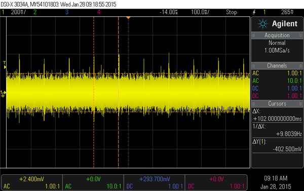
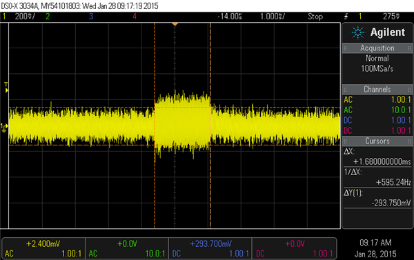
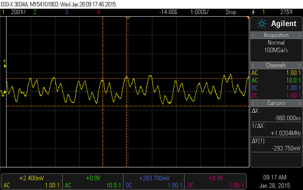
    Thanks for the quick response. The DC is when wifi is transmitting. I have attached a few waveforms below. The spikes are observed when wifi is transmitting. I further zoomed in in the following graphs. As you can see there is an inband signal of 1MHz which cannot be removed with filters. 

    Do you have OPA355 EMI characteristics? Can you recommend a similar Opamp that is EMI hardened.

    Thanks 

  • I can recommend an op amp with better EMI performance if I know some of the other requirements for your system. What bandwidth does the transimpedance amplifier need to achieve (also the photodiode capacitance will be needed) and is the OPA355 also used for the gain of 20 amplifier?
  • Hi John,

    I have a gain of 420K in first stage and about 20 in the second stage. I use the same opamp (OPA2355) in the board. I have 15V, 4.5V, 1.8V available on the board. 

    I have a strict risetime requirement of 300nSec at a signal of 1MHz. I use the circuit in transimpedance configuration. 

    Thx

  • KT, the photodiode capacitance is required to calculate the op amp gain bandwidth required. Please see section 2.4 in this TIPD: www.ti.com/.../tidu535.pdf for an explanation why. If you do not know the capacitance, alternatively you could give me the photodiode model number or datasheet and the reverse bias voltage.
  • Capacitance of the PD is 30pf. It is a big one. 

  • For this photodiode capacitance I estimate the op amp will need to have a GBW > 88.5MHz. At those bandwidths its unlikely to find any part with EMI hardening. This problem will need to be addressed externally using the tips I mention above. Another fantastic resource for dealing with these issues is the book Electromagnetic Compatibility Engineering by Henry Ott.
  • The fastest device with EMI filtering is the LMV861/862 (30MHz), followed by the LMV881 (23MHz).

    Adding EMI filtering to an amp increases the input capacitance - which is a "Bad Thing" with high-speed circuits.

    The LMV86x has 15pF and 21pF Cc and Cd respectively (LMV881 at 15pF) , so you would have to add a lot of compensation to prevent peaking, which kills your bandwidth. They were mainly designed for lower frequency circuits with moderate gains.

    This is why you do not see high speed amps (>50MHz) with EMI filtering. Of course, no amount of "filtering" will remove noise within the passband of the circuit without affecting the desired signal. So you need to reduce the reception and ingress of the external noise as much as possible.

    Tight layout and good RF grounds will do more than picking a EMI protected amp at these speeds...and this is info all covered in John's references.

    Regards,