This thread has been locked.

If you have a related question, please click the "Ask a related question" button in the top right corner. The newly created question will be automatically linked to this question.

OPA1652 Output Voltage and Current Tolerance

Other Parts Discussed in Thread: LF347, OPA1652, OPA4172

Hello,

Our customer is trying to replace a LF347 operational amplifier with the OPA1652.
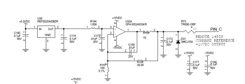
Circuit implementation < below >.

The circuit output labeled as PIN_C is an external connection point to the product.
This PIN_C is part of an external cable assembly so testing is done to evaluate shorted wires.
The specific test step was when the 24VAC source was shorted to the PIN_C connection.

I see in the datasheet absolute maximum rating “Input Current (All pins except power-supply pins) +/- 10mA
Customer does not think they can increase the resistance enough to limit to only 10mA into the OUT pin.

The OPA4172 has also been discussed for a replacement to the LF347.
In its datasheet it states only for “Signal Input Terminals” Current +/-10mA.
Nothing stated about the output pin.

The LF347 doesn’t even spec this.
Here is a link to the http://www.ti.com/product/lf347

? Would you have some suggestions on how to fix this?
? Or would you have a 36V, high output current drive opamp they could consider?

Thank you, Keith

  • Keith,

    The Absolute Maximum Ratings table shown in OPA1652 datasheet refers to a normal operation of the op amp where the signal is applied to the inputs which in turn causes the output to be driven to a desired close-loop gain voltage. However, the test you describe drives the output pin beyond its rails which will cause forward biasing of the ESD protection diode between the output and its rails. Since all ESD diodes are designed to handle only ESD short duration spikes (few nano-seconds in duration), ESD diodes can only handle 10mA DC current.
    Thus, in case of 24VAC test at the output this would require 900 ohm series resistance to limit the current to 10mA; (24V-15V)/10mA - this limitation applies to almost all op amps and not just to OPA1652 since ESD event metal traces are not laid out for high current loading.
    You may recommend to the customer to consider using OPA1652 in a single supply (0V, +36V) configuration if this is possible in their application. BTW, 10 ohm series resistor shown in the circuit will also be insufficient to drive reliably 0.1uF capacitor - the output voltage will most likely be oscillating.
  • Hi Keith,
    D31 has a reverse clamping voltage of 16.7V-18.5V so the output of the OPA1652 should never reach 24V unless the 24Vac souce can supply 61.5A (according to the SMCJ15A datasheet). What about selecting a model for D31 which has a reduced clamping voltage such as SMCJ12A (13.3V to 14.7V)? This shouldn't affect circuit operation since the output voltage looks to be a DC voltage of 10V.
  • When the dual feedback path is taken into account, TINA simulation indicates this circuit is indeed stable (>80 degrees of phase margin.)