This thread has been locked.

If you have a related question, please click the "Ask a related question" button in the top right corner. The newly created question will be automatically linked to this question.

4 to 20 mA Current Loop Transmitters using lm358

Other Parts Discussed in Thread: LM358, XTR117, XTR115, XTR116, OPA317, TIPD158

Hello,

I want to design a current loop transmitter circuit using the lm358 as the datasheet says it's possible. But there is no reference design how this work. How can i maintain a standard 4-20mA output for a large current loop which will be stable even if loop resistance differs from standard 250Ω? Help me please.
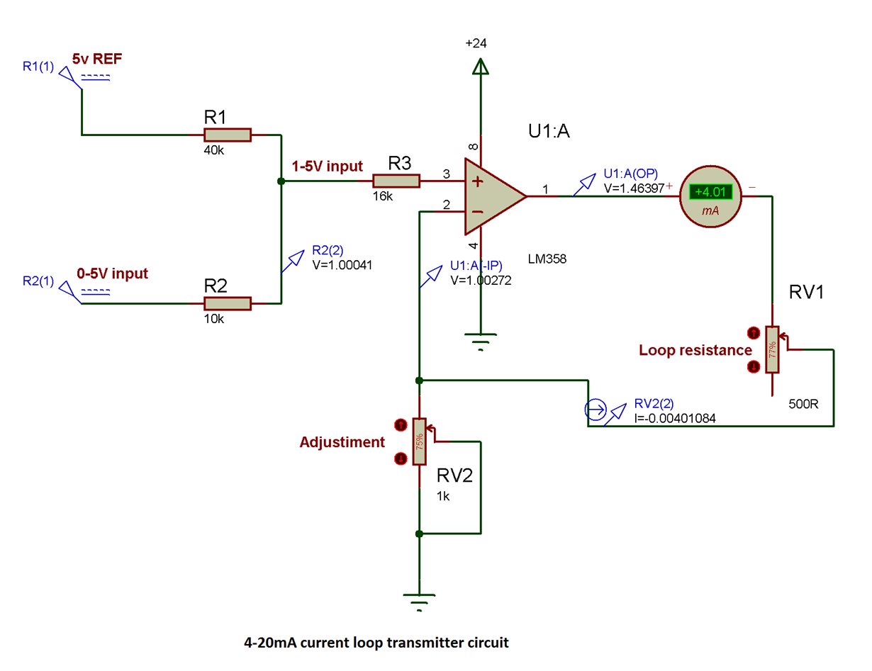
Here i have designed very simple one but i'm not sure about the stability of this with varying loop resistance. How could i improve this?

Thanks to all
Tarun

  • Hello Tarun,

    This is not a recommended circuit for a 2-wire 4-20mA transmitter.  You should really use the more "standard" configuration which is featured in TI's XTR115, XTR116, and XTR117 products.  The circuit is also featured in the reference design: TIPD158 which showcases a discrete 2-wire 4-20mA transmitter circuit EMI/EMC protection.

    Also, consider a newer amplifier with lower quiescent current so you have more current available for your sensor and signal conditioning circuitry.  Consider the OPA317 which was featured in TIPD158.

    Finally, consider reading through some blogs we recently published about 2-wire sensor transmitters:

    2-Wire Transmitter Blog Series

  • but how can i accomplish a 4-20mA current transmitter circuit using lm358 as stated on datasheet. Please give light on this. Thanks for your kind reply.
  • Hello Tarun,

    You can replace the OPA317 with the LM358 in the circuit featured in the reference design: TIPD158

    As mentioned before, consider using the XTR117 which integrates many elements of the circuit featured in TIPD158.