A related question is a question created from another question. When the related question is created, it will be automatically linked to the original question.
If you have a related question, please click the "Ask a related question" button in the top right corner. The newly created question will be automatically linked to this question.
Hello Manuel,
It looks like a model for the THS3092 was never created and the datasheet has an error. The THS3091 is a close substitute to the THS3092. You could try using that to do some basic simulations with the caveat that its BW is going to be a little higher than the THS3092, however their relative behavior is fundamentally the same.
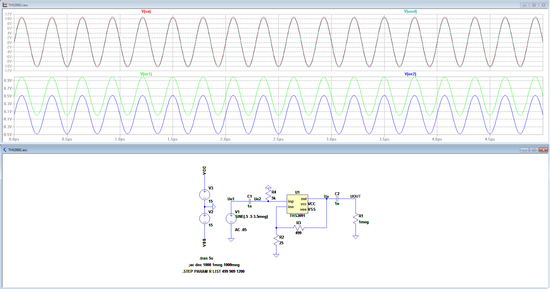
Another question has come up during simulation now. When I use the opamp in the non-inverting configuration it works as expected. The Signal I have, has a DC offset though. I tried to just block that with a capacitor but then the input of the opamp starts to float around 15V. I haven't seen this behaviour with other opamps(AD815). Does this have to do with the relatively smaller Input resistance (1Meg vs 7Meg). Can you think of a reason or a way to fix this? Is a pulldown-resistor the right approach?
Hello,
You do need to have some kind of resistance to set the dc bias point after the ac coupling. In addition to setting the dc bias point, the amplifier has an input dc bias current. If there is no resistive path on the non-inverting pin, then that current continuously flows into the input capacitor which will cause the voltage to start drifting towards a supply rail (depending on the direction of bias current). This is because I=C(dV/dt).
With the 5k resistor to GND you will see an output offset of 5k*4uA(Typical)*21(Gain of amplifier) = 20mV * 21 = 420mV. If this offset is too much you reduce the size of the resistor to 1kOhm.
If you are going to ac couple the output then that 1Meg resistor should remove the output offset and you will be fine. Just remember that the next stage input bias current (if it is an amplifier) will now flow through the 1meg resistor and create another offset voltage. If the next stage amplifier has a JFET or CMOS input, you will be fine since their input bias currents are usually in the sub-pA range.
thanks for the reply. I think I never thought about the bias current that way. I always thought of it as something going into the opamp but obviously it can flow the other direction as well. The output resistor of 1Meg was just simulating an open output, there will be a different load in my application.