This thread has been locked.

If you have a related question, please click the "Ask a related question" button in the top right corner. The newly created question will be automatically linked to this question.

Core specifications for DRV421

Other Parts Discussed in Thread: DRV421, DRV421EVM, DRV401

Hi to all !!!

I'm trying to develop cores to be used with DRV421 for both current measuring and ground fault detection in the range 30mA-30A, DC to 10KHz.

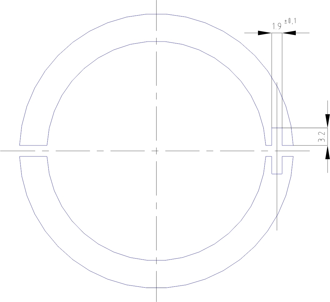
At the moment I'm using Nichel-Iron mumetal strip wound cores (from 30 to 110mm ID) and I asked the manufacturer to cut the core in two halves (2 "C"), milling one side to realize the DRV421+PCB slot, re-annealing (if necessary), and reclosing the core with a 0,2mm total gap (0,1mm in both cuts). Drawing attached.

I'm waiting for the samples to test them with a DRV421EVM. Estimated production could be 5kpcs/year (or more, I hope ...)

The procedure seems to be quite expensive and the manufacturer suggested me to choose a laminated core solution instead of a strip wound core, but I suppose that mumetal will not be the best choice to be cutted, handled and stacked to build the core. I should probably switch to Silicon-Iron laminations, but I'm afraid that they will not reach the same measurement accuracy, particularly at low currents.

I can't use ferrites or any synterized material, because of "economic" constraints.

I'll be grateful if you can give me any suggestion about materials, techniques and details, in order to realize mumetal or Silicon-Iron cores to be used with DRV421.


Moreover, I would like to ask you if there is the possibility to realize fluxgate current transformers using ungapped saturable cores, using a DRV401 with a fluxgate winding directly wound on the core. I have found various fluxgate solutions using 2 cores or 1 wounded fluxgate core with a magnetic shell and an external compensation winding, but I don'know if the DRV401 can fit these solutions.

Thank you very much for the help,

have a nice day,

   Giovanni

  • Giovanni,

    Let me get some confirmation on a few things to get you a complete answer.

    Regards,

    Javier

  • Giovanni,

    There are two different strategies needed to measure higher current or lower current such as the ground fault detection.

    For the ground fault detection the concerns are eliminating external magnetic fields that can cause errors when trying to measure low magnetic fields. This will be helped by an external magnetic shield and this will add cost. Eliminating Common mode current rejection, which is when both the supply and return current change quickly. This is also helped by adding an internal shield inside the core. Without these it will be very difficult to achieve the specifications you desire of the 30mA differential current.

    From the drawing I assume you have two air gaps. One on the side where the DRV421 is located and another which is on the opposite side of the DRV421. You would only want the air gap to be present on the side of the DRV421 and no gap on the opposite side. The air gap is also really close we normally suggest somewhere in the range of 0.5mm due to manufacturing limitations and being able to calculate the cross section area of the gap to calculate its reluctance. The reluctance at the air gap should be >> than that of the core reluctance. I can assist you with this once you give me the thickness of your core. This will also help you decide which core material you can use for you size constraint. Another limitation on the material you use is the rejection of external fields. You need a higher permeability material in order to have a greater rejection of neighboring fields.

    I have some FEMM simulations I can share with you that can help guide you in the selection of materials and design. Given the thickness of your core design and material permeability you are considering I can simulate and share results. FEMM is a free tool you can use to simulate your magnetic core and get a good idea of how it will behave.

    The DRV401 cannot drive a high inductance caused by an ungapped core.

    Regards,
    Javier Contreras
  • Hi Javier, thank you very much for your precious help !!!

    I downloaded the FEMM software, and I'm very interested in your simulations: it seems to be a very powerful tool.


    Here are some specifications of material and cores I would like to realize for ground fault detection.


    Strip Wound mumetal core:

    - mumetal foil thickness: 0,2mm

    - relative initial permeability: 46000 (Heff=0,004A/cm)

    - relative maximum permeability: 90000 (Heff=0,02A/cm, B=0,33T)


    Core dimensions:

    - Internal Diameter (ID): ranging from 30 to 110mm

    - Core Width (x-axis OD-ID): 5mm

    - Core Height (z-axis): 20mm

    - Core Cross Section: 100mm (5mm x 20mm)


    Some questions:

    1) From your answer, I assume that the best solution will be to realize only one gap in the core, but our core manufacturer says it will be very hard for him to cut a gap lower than 2 mm. In such a way I sould realize a very large number of turns to obtain a 200mH Inductance (minimum for stability). Is there a reason why a "two gap" core will not properly work ?

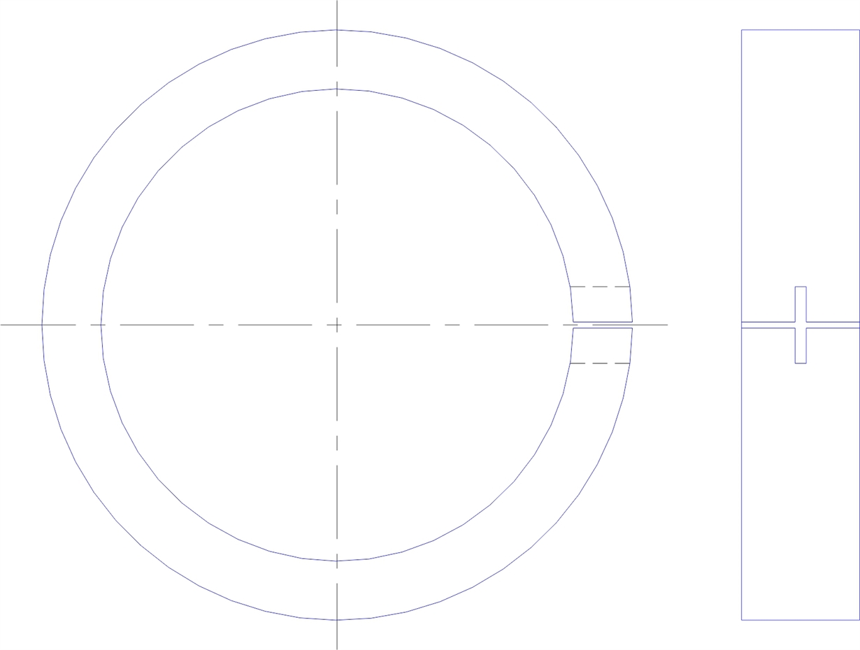
    2) DRV421 will work if the slot in the core will be realized "ortogonally" in the (z-y) plane (20mm core Height) instead of (x-y) plane (5mm core Width) ? Obviously, the DRV421 chip will remain parallel with flux (ortogonal to gap). See attached picture.

    3) The external + internal magnetic shield you suggested to realize, could be realized with the same mumetal foil I will use for the core ?


    Thank you for your help.

    Have a nice day,

      Giovanni

  • Giovanni,

    Sorry for delay but I did not have time to fully work on this today.  I have attached some simulations that you can see and adjust.  I wanted you to see some simulation and play with them.  I will modify some of them tomorrow and send you updated version.  If you need assistance with this tool we can also go over some of the tool.   I will add the foil inside the shield and simulate and show the difference vs other solutions.

    Center_slot_core_0p5mm_AirGap.FEM

    Center_slot_core_AirGap.FEM

    Center_slot_core_One_AirGap.FEM

    Regards,

    Javier

  • Thanks a lot, ... great !!!

    This morning I opened your simulations with FEMM tool and they seems to be very interesting ... but I think I need to take some time to study the tool features before starting to play with them and becoming able to understand the important differences between solutions and their "hidden details".

    Take the time you need to set up new simulations: you are really giving me a great help !!!

    Let me take some time to study the tool ... moreover, next week I hope to have quotations from manufacturers for strip wound and/or stacked laminated solutions.

    Have a nice day and ... happy Easter !!!

    Giovanni
  • Good morning, Javier.

    I have taken some time to review Maxwell's equations and studying the really powerful FEMM tool.
    During this time I received a gapped mumetal strip-wound core with a quite large slot where I have inserted the DRV421EVM circuit:
    - it works well at high currents (45Arms full scale, with original values)
    - it seems to work well at ground-fault currents too (good signal at 30mA, resolving 1-2mA, with R1=600Ohm)

    But ... as you stated in your first answer, it is now clear to me the need for an electromagnetic shield for both external and "common mode" internal fields: the position and geometry of the current-carrying cables (internal or neighborhood) makes the sensor see important "ghost signals" althought the ground fault current is null.

    My next step will be the realization of mumetal (0,2 and 0,5mm) shields:
    - external shield: rectangular parallelepiped, with hole
    - internal shield: cylinder

    I would like to ask you if there are some keyponts to respect in the realization of these shields, such as:
    - should the shields be connected toghether ?
    - should the shields be "closed" or "open" to avoid eddy currents ?
    - shoud the shield be connected to circuit GND or should they be left floating ?
    - ...

    Thanks a lot for your precious suggestions and have a nice day !

    Giovanni
  • Giovanni,

    I am glad to hear about your progress. Regarding your questions please see below. Some other comments. I assume the internal shield is thinner? Please simulate the shield with your core to make sure you see what you are looking for. I would add an external current source to make sure it is shielded your specifications. I would also place a differential currents in the simulation to see the results of the common mode current rejection . The inter-shield is for when you want to make a differential measurement of two currents through the magnetic core. I don't think it will work for the higher current measurement.

    - should the shields be connected together ?
    No. These are two separate shields. They are not really shields as you would think normally. These shield don't have potential but rather concentrate or divert the magnetic field.

    - should the shields be "closed" or "open" to avoid eddy currents ?
    I do not think you need to worry about eddy current but I will verify, but I think closed to shield better.

    - should the shield be connected to circuit GND or should they be left floating ?
    Floating. This is only for magnetic for the field to travel through the material.

    Regards,
    Javier
  • Thanks a lot, Javier !!!


    I send you two modified simulations, where I changed the core relative mu to 40000 (initial permeability of mumetal) ... I hope it is correct ...

    In the first one, I tried to implement a cylindric external shield (mumetal, 0,25mm) with an external neighbor current-carrying conductor. With high external current (300A), it seems that the core field is almost not affected.

    In the second simulation, I moved the neighbor conductor into the core and I have implemented a cylindric internal shield (mumetal, 0,25mm). When the two conductors carry an equal and opposite current (low or high), the core flux is almost zero and does not depend from the conductors position. Without the shield, the worst-case seems to be when the second conductor is close to the gap ...

    Please, let me know if my considerations are correct or not (I suppose I need to study some more ...)

    Have a nice day,

       Giovanni

    Center_slot_core_0p5mm_One_AirGap_Int_Ext_Shield.zip

  • Giovanni,

    This is what I meant.  I think you got it and understand.  I hope the simulations showed you exactly what you needed to see? 

      If you are increasing the Rshunt for the ground fault version to increase the gain please keep in mind to connect back to back diodes across the resistor to make sure the degauss function better.  Increasing Rshunt limits the amount of current during the degauss function.  Also do not increase Rshunt that could cause a voltage drop greater than the forward bias voltage of the diode.  I am not sure leakage current to expect on the diodes but that will vary with diode. 

     If we need to clear things up more let me know.  We can elevate to a call if needed.

    Regards,

    Javier

  • The back to back diodes is a great suggestion !!! I will try it today ... at the moment I'm working without shield, so, when I move the core the linked earth field changes and is very difficult to evaluate if the degauss function properly works. I'm sure that the antiparallel diodes will help on this job !!!

    ... let me ask you for the "tip of the day" ... :-) !!!

    I would like to realize a 4 wire sensor (VCC, GND, Vref, Vout) and implement the Degauss function by pulling Vref to GND ... do you have any circuit suggestion ???
    At the moment I only added a 2N7002 in the following way (with respect to the DRV421EVM schematics)
    Source connected to Vref wire, which is the common point between R3 (2k4) and R4 (470R);
    Gate connected to REFOUT (R4);
    Drain connected to DEMAG (R12 10k).
    When I pull down the Vref pin to GND, Vgs=2,5V and the MOSFET will turn on, pulling down the DEMAG pin too; when I release the Vref pin, Vgs=0V and the MOSFET will turn off releasing the DEMAG pin, so the Degauss function should start.

    Could it be a good solution, or do you have any circuit to suggest me ?

    I'm very interested to have a call with you, via telephone or via Skype: I don't speak english very well, but I can speak Spanish, if it helps ...

    Thanks a lot and have a nice day !!!
    Giovanni
  • Giovanni,
    Sorry for the delayed response. Could you please tell me the size of the Shunt resistor( R1)? Also I was waiting for the 2n7002 parts to test the circuit. I realized the VGS could go up to 3.1V and will not be active with a 2.5V signal. I will also attempt to come up with an alternative circuit.

    Please send me an email and we can schedule a call. j-contreras@ti.com

    Regards,
    Javier
  • Good mornig, Javier ! Don't worry and take the time you need ... you are really giving me a great help !!!
    R1 shoud be a 620Ohm 0,1% resistor (50ppm or better).
    Instead of the 2N7002 I can use a BC817 with a >10k base resistor.

    I will send you an email from my work email.

    Have a nice day,
    Giovanni