This thread has been locked.

If you have a related question, please click the "Ask a related question" button in the top right corner. The newly created question will be automatically linked to this question.

Tle2426 Configuration and how to use the split rails obtained using this IC

Other Parts Discussed in Thread: TLE2426, MC33063A, LM337, LM317, TL082

Hi all

I am having a single side supply of +15 v and i would like to obtain +7.5V and -7.5 V from this supply. As I was going through the datasheet of TLE2426 I came to know that  this can be used as a rail splitter where Vout= Vin/2 . In my understanding if we are giving (0-15V) suppy where peak to peak is 15V we will get +/- 3.75V (7.5 V P to P) which is half the input.

1. Is my understanding correct

2. If correct , is there any method to make +/- 3.5 to +/- 7.5V

3. How to use this split rails, whether we can give positive rail to +vcc and negative rail to -vcc of the ICs which require dual supply

Please help me in this regard as soon as possible

  • Hi Charles,

    Please see my comments regarding the TLE2426.

    I am having a single side supply of +15 v and i would like to obtain +7.5V and -7.5 V from this supply. As I was going through the datasheet of TLE2426 I came to know that  this can be used as a rail splitter where Vout= Vin/2 . In my understanding if we are giving (0-15V) suppy where peak to peak is 15V we will get +/- 3.75V (7.5 V P to P) which is half the input.

    The TLE2426 cannot directly create +/-7.5 V from a single, +15 V supply. What it can create is an output that is halfway between 0 V and +15 V. So employing the original +15 V, and 0 V (GND), a third level is added, +7.5 V. Relative to +7.5 V, +15 V is +7.5 V above it, and 0 V is -7.5 V below it. A +/-7.5 V supply is created, but its common is +7.5 V above ground. That isn't the same as a +/-7.5 V supply referenced to 0 V. In certain circuits this is usable; especially where the input signal is ac coupled.

    1. Is my understanding correct

    The TLE2426 is just a single supply splitter, and not used to create +/-3.75 V.

    2. If correct , is there any method to make +/- 3.5 to +/- 7.5V

    If you wish to create +/-3.5 V from a a +/-7.5 V dual supply, you can use a positive and a negative linear regulators. The LM317 positive and LM337 negative regulators are commonly used for this purpose. If you need to boost +/-3.75 V to +/-7.5 V, then a boost switching regulator such as the MC33063A can be used to create the higher positive and negative supply levels. You can find information about it here:

    www.ti.com/.../mc33063a.pdf

    TI has a Power Management E2E forum. The engineers monitoring that forum should be able to provide you information regarding the best solutions for your dual supply needs.

    3. How to use this split rails, whether we can give positive rail to +vcc and negative rail to -vcc of the ICs which require dual supply

    I think I have answered this in no. 1.

    Regards, Thomas

    PA - Linear Applications Engineering

  • Thank you very much

  • This is the circuit schematic that i ve made using TLE2426, please tell me whether it is right or wrong !

  • Hi Charles,

    The TLE2426 does not perform the function you are attempting to use it for. It is not capable of producing a positive and negative supply (+/-7.5 V) from a single positive supply (+15 V). Your circuit in the upper left will produce +15 V, +7.5 V and ground (0 V).

    Regards, Thomas

    PA - Linear Applications Engineering

  • Thomas,

    Can't you both be right.
    Your point of view is that the hatched (standard) ground symbol is ground.
    Charles' point of view is that the hollow triangle ground symbol is ground.

    The only catch is that one has to pick one view or the other. There is no switching back and forth.
    For example that 15V Vs supply had better be a floating supply in Charles' world
  • Roland,

    Yes that is the point . I am using the hollow triangle ground (7.5V) as reference to produce +7.5 V ( 15V) and -7.5 V (0). But I am still confused the way i have used it to power the opamp circuit . Can you please confirm the circuit in this regard.

    Charles
  • Hi Charles,

    The TLE2426 is intended to create a virtual ground halfway between V+ and ground (0 V). In the case of your circuit you would have V+ at +15 V, the virtual ground at +7.5 V, and V- at 0 V. The +7.5 V/-7.5 V labeling in your schematic was confusing me about your expectation of the TLE2426.

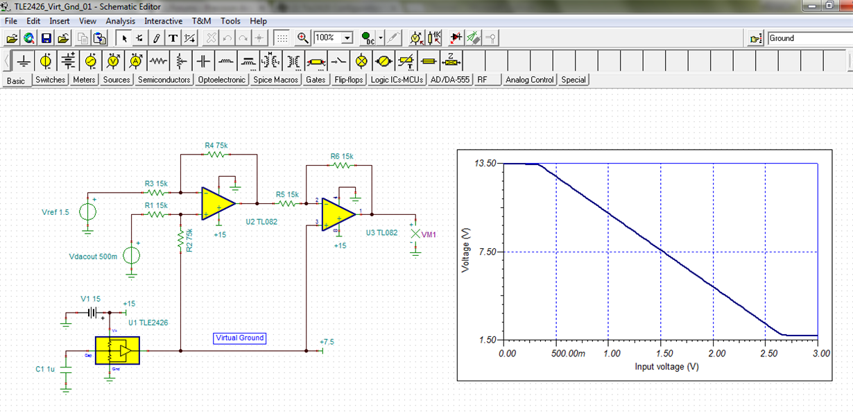
    I have set your TLE2426/TL082 circuit up in TINA for simulation purposes. I do not know what your DAC output voltage is supposed to be so I just swept the voltage upwards from 0 V. You can see that the linear input range for your circuit is from about 0.35 V to 2.65 V. Voltages outside that range are limited by the output swing range of the TL082.

    You can use the attached TINA circuit if you would like to try different simulations.

    Regards, Thomas

    PA - Linear Applications Engineering

    TLE2426_Virt_Gnd_01.TSC

  • Thank you both Roland and Thomas !

  • Hi Charles,

    We are glad to help. I hope you are now on the right track with your TLE2426 application circuit.

    Regards, Thomas

    PA - Linear Applications Engineering