This thread has been locked.

If you have a related question, please click the "Ask a related question" button in the top right corner. The newly created question will be automatically linked to this question.

50Hz oscillation at the output of LMP8358

Other Parts Discussed in Thread: LMP8358, OPA2735

Hi all!

We are using LMP8358 as amplifier for pressure sensor , meanwhile, 50Hz oscillation or interference is observed at the output of amplifier. Short introduction of the application and test procedure and results are as following.

  • Application

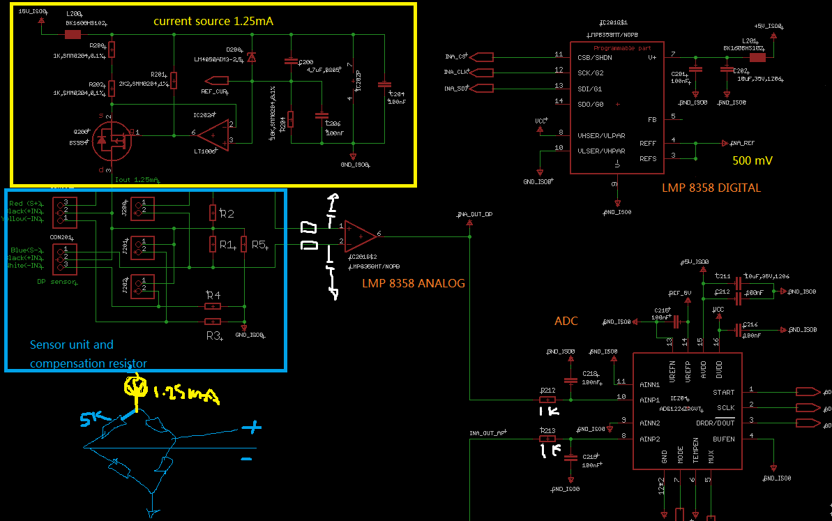
1.25mA constant current through resistance bridge (pressure sensor, each bridge ~ 5kohm), differential outputs connect to the input of LMP8358, the output of amplifier connects to the ADC with a RC filter in between.

circuit

  • Problem

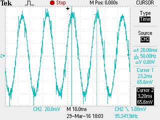
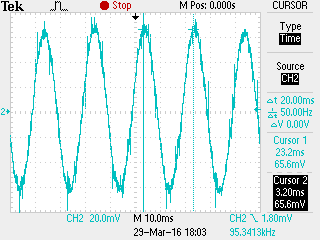
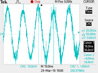
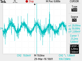
    at the output, 50Hz oscillation (amplitude: +-60mV or even larger) coupled, when the gain set at 1000. When the gain at 500, the amplitude is smaller, and the gain at 100, the amplitudes is smaller than the gain at 500. Probe at the INPUT, can not observe the 50Hz.

     -gain: 1000x

    -gain: 500x

    -gain:100x


  • What have been done
  1. put 10 nF cap at both input of amplifier – no help
  2. put RC (10k + 10nF) at the input – no help
  3. put RC (1k + 1uF) at the output of amplifier – no help
  4. put RC (6.8k + 1uF) at the output of amplifier – no help
  5. use resistor bridge instead of real sensor – no help, exclude the sensor problem
  6. use the other PCBA – no help
  7. put the sensor to the older version circuit, which uses OPA2735 with gain 15, no 50Hz can be observed.


Thanks for all the suggestion!  for any questions, pls write below, thx!

Jason

  • Hi Jason,

    From the circuit provided you are acquiring a very low frequency AC, sometimes referred to "varying DC".  It does not appear to me that you have any kind of filtering on the "front end"; the first thing I would do is figure out your max "frequency" and make the first stage a low-pass filter with a roll-off of *something* like 10Hz (or less). That will take care of some of the 50Hz. Realize that 50Hz. (your AC line frequency?) is everywhere. This is being coupled into the sensor and with the kinds of gains you are using it is not surprising to see this.  I'd bet that the "old" boards exhibit this as well; big difference between a gain of 15 and a gain of 1000.

    Secondly, is there a cable involved with this arrangement between the input to the circuit and the board? If so, how that cable is constructed is critical to the performance and susceptibility to extraneous fields. Typically, one would use a shielded cable with the shield braid connected at the "board" end only

    Using plenty of decoupling around the opamp; 0.1µF ceramic in parallel with a 10µF tantalum, through a 10-100Ω series resistor from the supply.

    You're using much higher gains than you did previously; board layout is critical to the performance of this kind of circuit.

    50Hz. is telling in that this is being coupled from a local emitter. If the power supply is on the board under test, try separating them for a test. If it was getting from the power supply I'd expect to see 100Hz. (full wave rectified).

    If you have a "good" scope, I would look at the ground differentially and see if the entire module isn't being affected.

    Lastly, and not something I would recommend is a 50Hz. notch filter. In some cases this is unavoidable; in many cases it is a band-aid and should be used as a "last resort".

    Do you have a photo of the module under test with interconnects? Seeing this would help try and spot where the signal is being affected.

    Mike T.