This thread has been locked.

If you have a related question, please click the "Ask a related question" button in the top right corner. The newly created question will be automatically linked to this question.

INA170 Current Direction Problem

Other Parts Discussed in Thread: INA170

Hello,

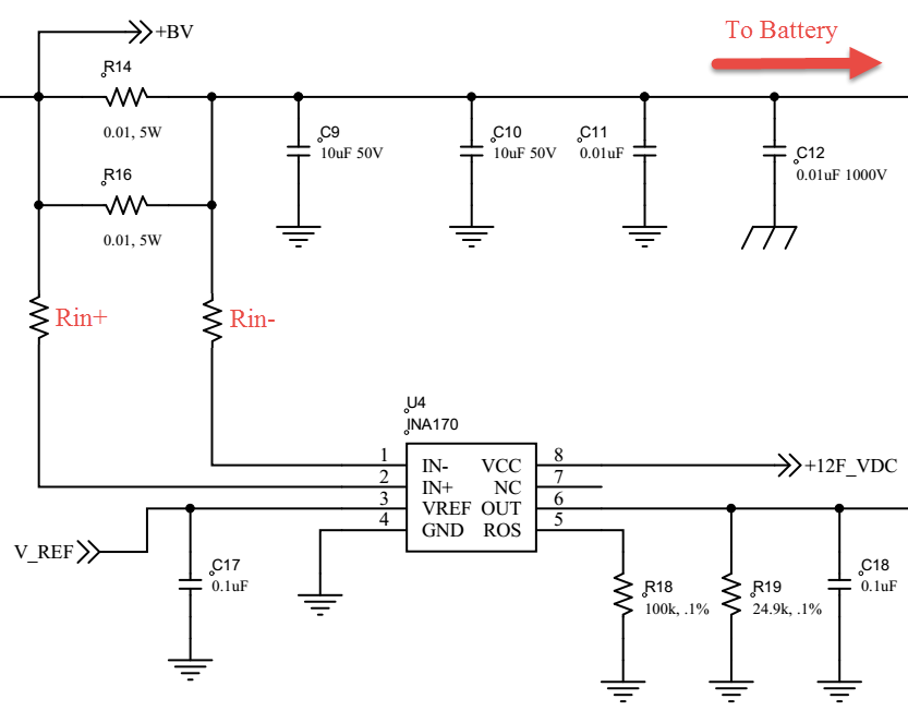
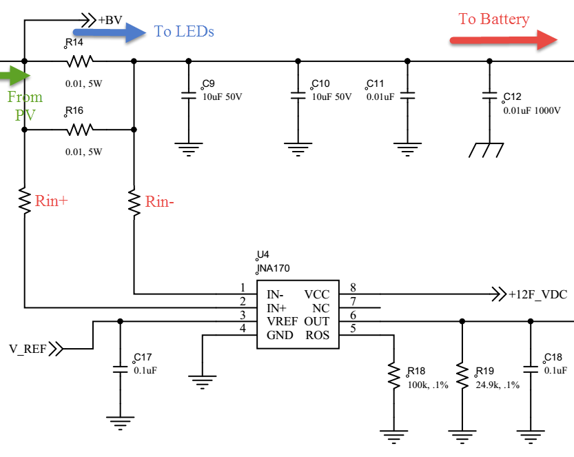
I've got an INA170 used to measure bi-directional current flow to and from a 12V battery. The battery is either charging from a PV panel or driving an LED load, never at the same time. When charging the battery the current monitor works well. On the other hand, when the current is flowing from the battery to the load, I'm noticing a significant voltage drop on the trace leading to IN+ (pin 2), which I labelled Rin+ below. Rin+ and Rin- are not actual resistors, just pasted in to the diagram.

With a 12mV drop across R14/R16 I'm seeing around 2.5mV across Rin+ and nothing across Rin-. Unfortunately, the kelvin connection between R14/R16 and IN+/IN- is not ideal, but it appears to be Ok when current is flowing to the battery.

I initially thought it could be due to input bias current, but the fact that it only appears on one input and and only when current flows in one direction makes that seem unlikely.

V_REF is 5V.

Any ideas what could cause the voltage drop on Rin+?

Thanks,

Ian

  • Hi Ian,

    I received your question. Will review and get back to you ASAP.
  • Hi Ian,

    Did you tried disconnecting the BV+ (PV Panel) and measured the drop on IN+? You have a switch there? How the system selects when to use the Battery and when to use the PV Panel?

    Also, you said RIN+ and RIN- are NOT actual resistors. How are you measuring the drop?

  • Hi Mayrim,

    For clarification, +BV leads to an LED load, and the PV input comes in at the same junction on the schematic. I updated the schematic below.

    Yes, I have tried measuring the drop to IN+ with the PV disconnected. When I do this I notice the drop across trace Rin+.

    Yes, there is a switch in line with the PV panel input controlled by PWM. The system measures voltage across the PV, and when it crosses a threshold it PWMs the PV panel.

    I measured the drop across the traces (Rin+ and Rin-) with a Fluke DMM. One probe at the INA170 pin and one at the correct R16 pad. The voltage drop here was quite stable when there was one. As I mentioned this voltage was only present when current was flowing from the battery to a LED load, not when charging the battery.

    Thanks,

    Ian