This thread has been locked.

If you have a related question, please click the "Ask a related question" button in the top right corner. The newly created question will be automatically linked to this question.

XTR105 Fails with EFT test

Other Parts Discussed in Thread: XTR101, XTR105, TIPD161

I'm using XTR01 for 0-150°C to 4-20mA current converter. Recently I have replaced the XTR101 circuit with XTR105 & the out put are satisfied with the new chip. While conducting EFT test with the new XTR105 circuit, it fails at 2KV capacitive coupling EFT test, where the XTR101 can pass the EFT test @ 2KV. I have attached the schematic of XTR105 & the protection circuit same for old XTR101.

Do you have any recomendation for the protection circuit. The same circuit withstand 2KV signal surge. Only fails at EFT.

Udhay

  • Hi Udhay,

    First, what kind of failures did you experience on your system?  Did the circuit fail because it was damaged?  Do you have to reset the modules to return them to normal performance?  Or, do the modules experience deviations outside of a particular level that is unacceptable?  Any information you can provide will be helpful.

    That said, take a look at the reference design:  TIPD161.  It's a PT-100 to 4-20mA 2-wire transmitter reference design using the XTR105.  We took the design to a local certified test house to observe its performance when exposed to the IEC61000-4 tests.  The test results are shown in the TIPD161 design guide.  The results were positive for both 2kV and 4kV EFT with the protection scheme shown below, it looks similar to yours with a few components in different places.  PCB layout can also impact the results of the performance of these tests as well so take a look at the PCB layout files for TIPD161 and try to implement similar techniques.

  • Hi collin,

    Thanks for the reply. I feel very happy that the device can withstand for upto 4KV EFT & the document you have shared is very useful for me.
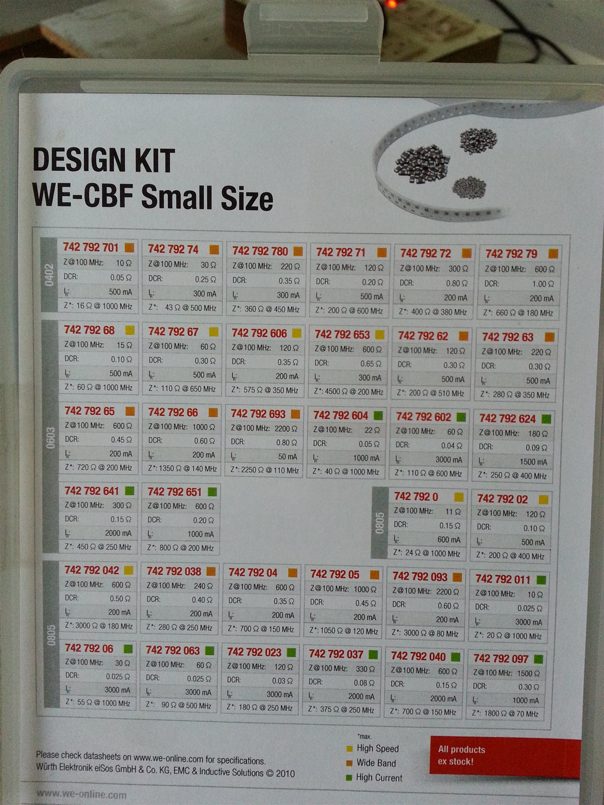
    While I'm doing my EFT test with 2KV level, my XTR105 IC got damaged. Initially I started my design as per my previous circuit attachment without the ferrite bead (replaced with a 0E resistor). At the time the circuit fails at +2KV EFT. After that I placed a ferrite bead (742 792 693) & now its failed at +1.5KV.

    Unfortunately I don't have the ferrite beads you have mentioned as per your reference design. I have a wurth electronics ferrite bead design kit. Can you suggest me an equivelent part from wurth electronics? Or we have to use the same part as you mentioned? I have SMAJ33CA. Can I use it for my testing? Or we have to use the SMBJ40CA TVS diode? My supply voltage is +24V DC

  • Hi Udhay,

    As mentioned before, these tests are very sensitive to the PCB layout and cabling methods used during the testing. Could you share information about the type of cabling used during the tests as well an image of your PCB layout?

    For the ferrite bead, I think the 50mA current rating of the 742792693 may be too low. Try the 742792040 device, it looks similar to ones that have worked well for us.

    Regarding the TVS diode, it's best to use the lowest voltage TVS possible that your system can tolerate based on the maximum expected operating voltage. A 33V TVS diode will provide better protection to the design than the 40V TVS diode, provided the two diodes have the same power rating. I noticed you chose the 400W SMAJ series whereas the reference design has used the >600W SMBJ series. Lower power TVS diodes will have greater increases in their voltages during large surge type transients so consider trying the SMBJ33CA device.

    Finally we try to put the TVS diode as physically possible to the loop+/loop- connections on these designs to minimize PCB impedances that might prevent the TVS diode from diverting transient energy around the IC as desired. You've placed a few components between the TVS diode and the connector. Consider moving the TVS diode to the location of the MOV1 component.