A related question is a question created from another question. When the related question is created, it will be automatically linked to the original question.
If you have a related question, please click the "Ask a related question" button in the top right corner. The newly created question will be automatically linked to this question.
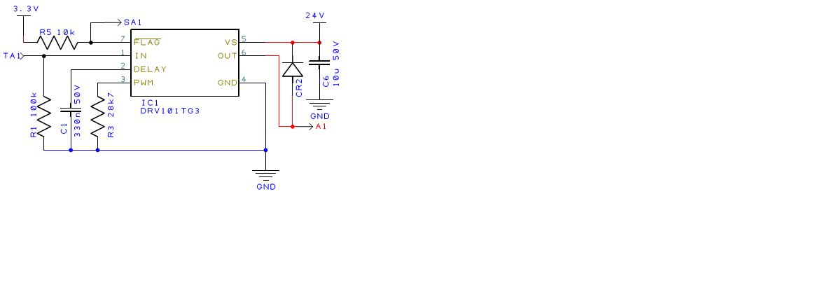
The DRV101 IN pin is intended to be driven by a digital source that can sink and source the current associated with the pin. In the Pin Descriptions table on datasheet page 4, it states,
"Pin 1 - Input - The input is compatible with standard TTL levels. The device output becomes enabled when the input voltage is driven above the typical switching threshold, 1.7V. Below this level, the output is disabled. With no connection to the pin, the input level rises to 3.4V. Input current is 20µA when driven high and 80µA with the input low."
It appears because you are allowing the pin to float the pin is sourcing current through the 100 K resistor and attaining a level of 1.9 V, indicating the pin is sourcing 19 uA through R1. That is believable because the pin rises to 3.4 V with no load attached.
Try reducing the value of R1 in your circuit; the voltage should drop as it is reduced in value. Or, drive it with a logic gate and the pin will follow the high and low output states of the gate.