Hi
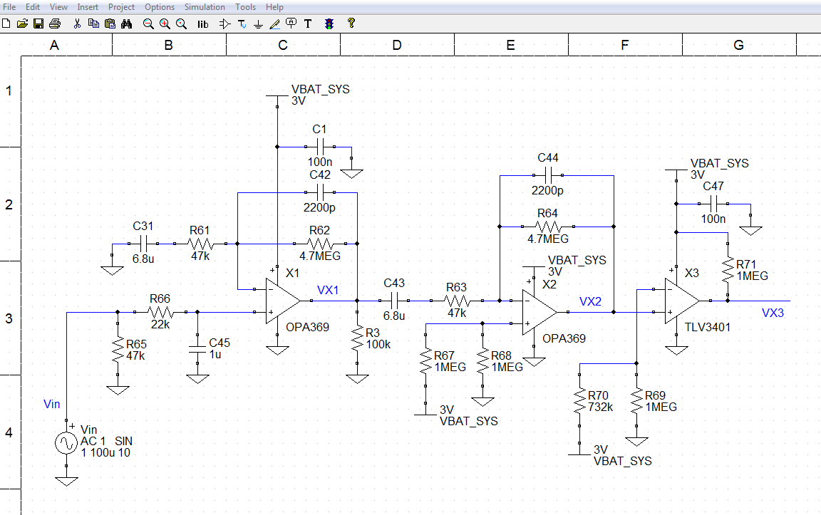
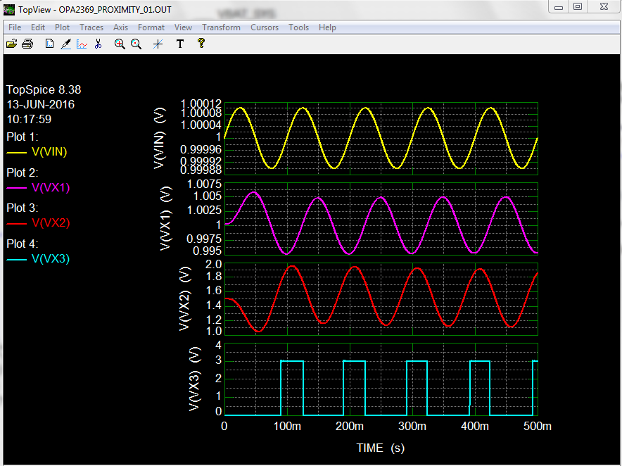
I am using below circuit to detect the motion of human body. I have tried to simulate the same in Pspice but not getting output. Also i wanted to give 0-5v (Differnet Values) plus on R3 or in parallel6332.OPA2369_PSPICE_AIO.zip to R4 in attached simulation files how i can do that. Also the First stage and second stage amplifier is not working.
Can you please check my simulation adn let me know where and what change i have to do to simulate my circuit.
---------------------------
Thanks
Krunal Shah