This thread has been locked.

If you have a related question, please click the "Ask a related question" button in the top right corner. The newly created question will be automatically linked to this question.

duty cycle control of power for an op amp

Other Parts Discussed in Thread: TLV521, LPV801, LPV542, LPV802

I am trying to get extremely low power consumption from an op amp. I've found the TLV521 which has a 350 nA typ. current consumption, but I want to try and drive that lower by power cycling it at ~10 Hz, since that's all i need to sample the output at. I can't find information on the initial power on for the device (or op amps in general), so I can't tell if this is feasible. Does anyone have an idea of the length of time required to achieve a stable signal?

Thanks,

  • HI Efret,

    It will take several milliseconds for the TLV521 to come into operation. I have not measured the 521 specifically, but it's cousins (LPV542, and the upcoming LPV801/2) take about 5ms to come into full operation and i would expect the 521 to be similar.

    Power cycling may actually use more power than just leaving it on. There is a turn-on supply current surge current on most amplifiers than can be as much as several milliamps for hundreds of nanoseconds.

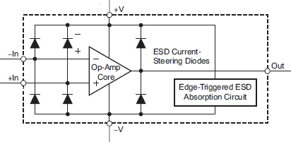
    There is also the power required to recharge the required minimum supply bypass caps (0.01uF minimum), and the charging/discharging of any coupling caps or ADC charge reservoir caps in the feedback or output sections. If the power supply falls to zero, the ESD diodes on all the pins will pull all the I/O pins down to ground, so the I/O nodes will not just simply 'float" until the next power cycle.

    The ramp rate of the supply also makes a big difference. One thing to watch is that if the ramp rate is faster than 1V/us (like driving directly from a digital IO pin), you can trigger the ESD protection circuits ("Edge Triggered ESD" in above) that are designed to clamp the supplies if a fast edge (ESD event) is detected.

    If you do use a I/O pin, place a diode in series to prevent the pin from discharging the bypass caps when low and just let the supply "droop" until the next cycle.

    Also - micro-power circuits usually use high value feedback resistors to save static power - so the higher impedance also add to the start-up delay.

    The upcoming 400nA LPV801 / LPV802 was specifically designed to minimize the turn-on current.

    SPICE models generally do not model the amplifiers turn-on current, but it can model the currents required in the feedback and bypass circuits.The trick is to check the "Use Zero Initial Values" (all simulators have this setting buried somewhere) so that the supplies start from zero instead of an ideal state. Then you can see the bypass cap charge currents and similar.

    Regards,