This thread has been locked.

If you have a related question, please click the "Ask a related question" button in the top right corner. The newly created question will be automatically linked to this question.

OPA365 stability issues

Other Parts Discussed in Thread: OPA365, OPA354, TIPD176

Dear Team,

We received the below question from one of our customer:

First, I would like to mention, that I have a solution for my problem. I am just writing, because I don’t understand why an oscillation with OPA365 occurs. Reading the datasheet, in my opinion the device should be stable in my circuit. I use OPA365 as in the schematic below: (Transimpedance Amplifier)

OPA365 oscillates, with kind of saw tooth @ 9MHz. See scope Plot below. Besides this oscillation the circuit works correctly.

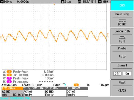
Because of the layout I get a few additional pF feedback capacitances, what limits the rise time of the circuit to about 160ns. That corresponds more or less to a bandwidth of 5 MHz. OPA365 should have almost 90° phase margin at 5 MHz, little less at 9 MHz, so it should be stable I guess.

When I replace OPA365 with OPA354 the circuit becomes stable. Could you please explain to me, why OPA365 oscillates? I would really like to understand that for further applications. Is it possible that I see the switching of the internal charge pump at the input?

Thank you in advance.

Kind Regards,

Mo.

  • Hi Mo,

    When transimedance amplifiers oscillate it is because the circuit's phase margin has been reduced to the point where it is zero degrees, and the applied feedback becomes positive. The phase margin reduction comes about because of phase shift introduced into the feedback loop by the pole that is created by the feedback resistor and the parallel combination of the op amp input capacitance and the photodiode junction capacitance. Photodiode junction capacitance can be quite high, tens to hundreds of picofarads, so it doesn't take a lot of feedback resistance to contribute a lot of phase shift to the loop. Often, a high reverse bias is applied to the photodiode so that it operates in a region where its junction capacitance is less.

    The usual way to compensate the circuit is to increase the feedback capacitance and that counters the phase shift introduced by the capacitances at the op amp input. The downside of that approach is that the bandwidth of the circuit is reduced and that may not be acceptable.

    The OPA354 is a wider bandwidth op amp than the OPA365 and the two have different gain-phase performances across frequency. Apparently, the OPA354 maintains enough phase margin in the circuit such that the total phase shift doesn't result in positive feedback.

    John Caldwell developed a TI Precision Design, TIPD176, "1 MHz, Single-Supply, Photodiode Amplifier Reference Design." It provides much of the information needed to successfully design a photodiode transimpedance amplifier. You can find the information here:

    Regards, Thomas

    PA - Linear  Applications Engineering

  • Thank you for your response.

    I thought about that too, but doubted it because my Circuit has a bandwidth limit of 5MHz. I decreased bandwith down to 1MHz, but the oscillation did not get smaller.

    I also seems strange to me, that it is not a harmonic oscillation. It's not like other amplifiers that oscillate on a single frequency. This saw tooth appears more like a periodic, internal clipping to me. Or as I wrote the influence of the internal charge pump.


    Wouldnt the oscillation get smaller if I decrease bandwith by increasing the feedback capacitor?
    And wouldnt it look like a sine wave?


    Best regards & thanks
    Rolf

  • Hi Rolf,

    I checked with some of our engineers who have more experience than me with the OPA365. I explained to them the ~9 MHz ripple you had observed at transimpedance amplifier output and they cast doubt that it is related to a loop stability issue based on your design. It turns out that the charge pump frequency is right in the range of waveform that you are observing at the output. It was explained that even though the charge pump powers both sides of the input differential stage that slight imbalances between the two sides can result in a small amount of the charge pump waveform making its way to the op amp output. 

    Adding a low-pass filter after the stage should help remove the ripple, but that may not be acceptable from a circuit bandwidth standpoint. If you can apply an alternate op amp such as the OPA354 that doesn't have the front-end charge pump, that would provide the easiest solution.

    Regards, Thomas

    PA - Linear Applications Engineering