This thread has been locked.

If you have a related question, please click the "Ask a related question" button in the top right corner. The newly created question will be automatically linked to this question.

Use LMH5401 for DC-coupled to interface ADS5400

Other Parts Discussed in Thread: ADS5400, LMH5401, TSW12J54EVM

Now I am using ADS5400 to capture the input signal.


The characteristics of the input signal is as follow:

1)      single-ended input, 50ohm;

2)      signal bandwith :500MHz;

3)      input voltage: -2V to +0.5V;

4)      DC-coupled;


And the input characteristics of ADS5400 is as follow:

1)      Differential input, common mode voltage of 2.5V;

2)      The input voltage at each pin of the differential input must be in range of 2.0V to 3.0V;


I ask a question at High Speed Data Converters Forum, and Richard P. advise me to use LMH5401 to achieve it and advise me to open a question at High Speed Amplifiers Forum.


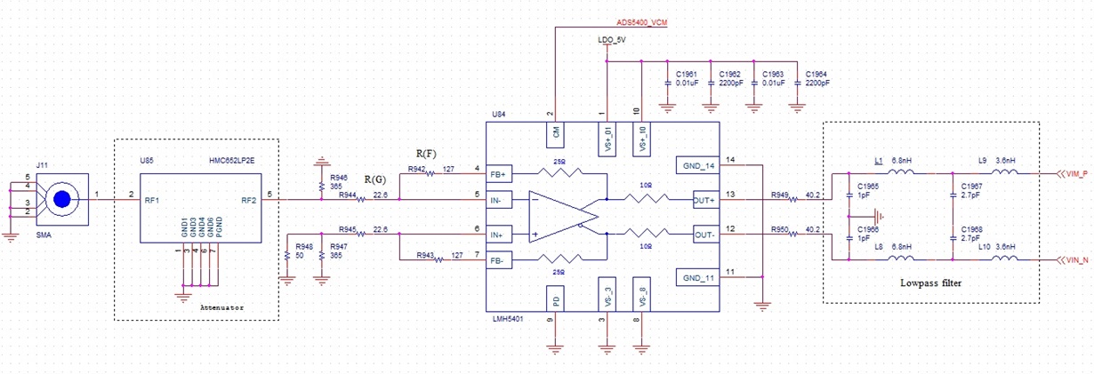
I find the input circuitry of TSW12J54EVM is similar to my requirement.


In datasheet, the gain of LMH5401 should above 2, so the output of LMH5401 is out of ADS400’s range.


I use an attenuator to attenuate the input signal of LMH5401.


Question 1:Can this circuitry work ok for my requirement?

Question 2:The gain of the LMH5401 shoule be set to ?and the optimal resistance value is ?


Question 3:Now the lowpass filter is 2GHz, if I need 800MHz, how to change it ?


Thanks!

Best wishes!

  • Hello Xiang,

    The LMH5401 is well suited for driving the ADS5400.  The gain should be set to 3V/V or higher and the feedback resistor should be 200 Ohms to 250 Ohms (175 Ohms to 225 Ohms external).  The TINA model will help with this as well.  

    I would recommend loading the TINA pogram and TINA model for the LMH5401.  

    With the TINA model you can set up the power supplies and the input attenuator.  You can model the ADC input as an equivalent resistor/capacitor.  

    The best way to redesign the filter is to find a demo or free copy of a filter design program.  I use the AADE Filter design software, but I think it may be out of date.  

    If you are a student you may be able to get free software with your student account.  

    This excel spreadsheet will help set resistor values.   Make sure to simulate in TINA your final solution.

    3312.FDA single to diff resistor calculations with BW and Noise calculations to share.xlsx

    Regards,

    Loren

  • Thanks for your help.

    I think with my application, The gain should be set to 3V/V.

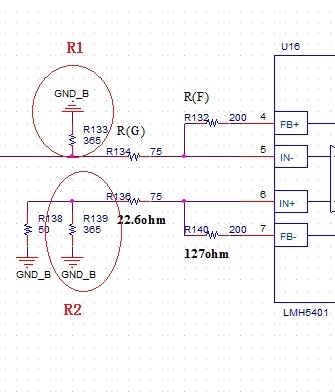
    So, the external feedback resistor is 200ohm and the gain resistor is 75ohm, the gain is = (200ohm + 25ohm)/75ohm = 3;

    But, I don't know how to calculate R1 and R2,

    Can you help me ?

    Best wish!

    xiang song.

  • Hello Xiang Song,

    Did you try the spreadsheet to set the resistor values?  Also, there is 25 Ohms of on chip feedback resistance, so R132 and R140 should be 175 Ohms for a total RF of 200 Ohms. 

    Regards,

    Loren

  • Hi Loren,

    Thanks.

    Now, if I can use two lowpass filters (LFCN-1000) between LMH5401 and ADS5400, so I don't need to design the filter?

    Thanks.

    Best wishes!