This thread has been locked.

If you have a related question, please click the "Ask a related question" button in the top right corner. The newly created question will be automatically linked to this question.

INA195: Device failure

Part Number: INA195
Other Parts Discussed in Thread: OPA197

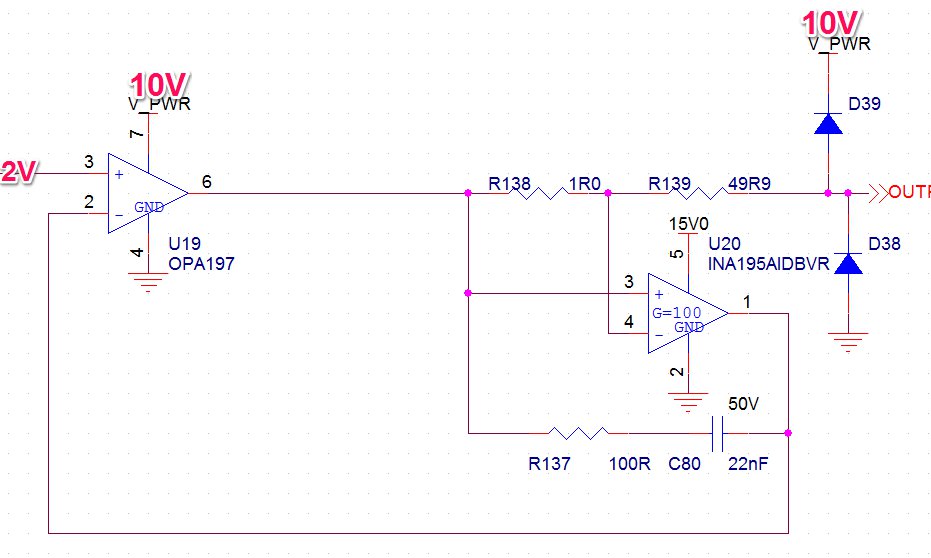
I'm having some issues with the INA195 in the following circuit configuration (there is also a 100nF decoupling capacitor for the INA195 not shown):

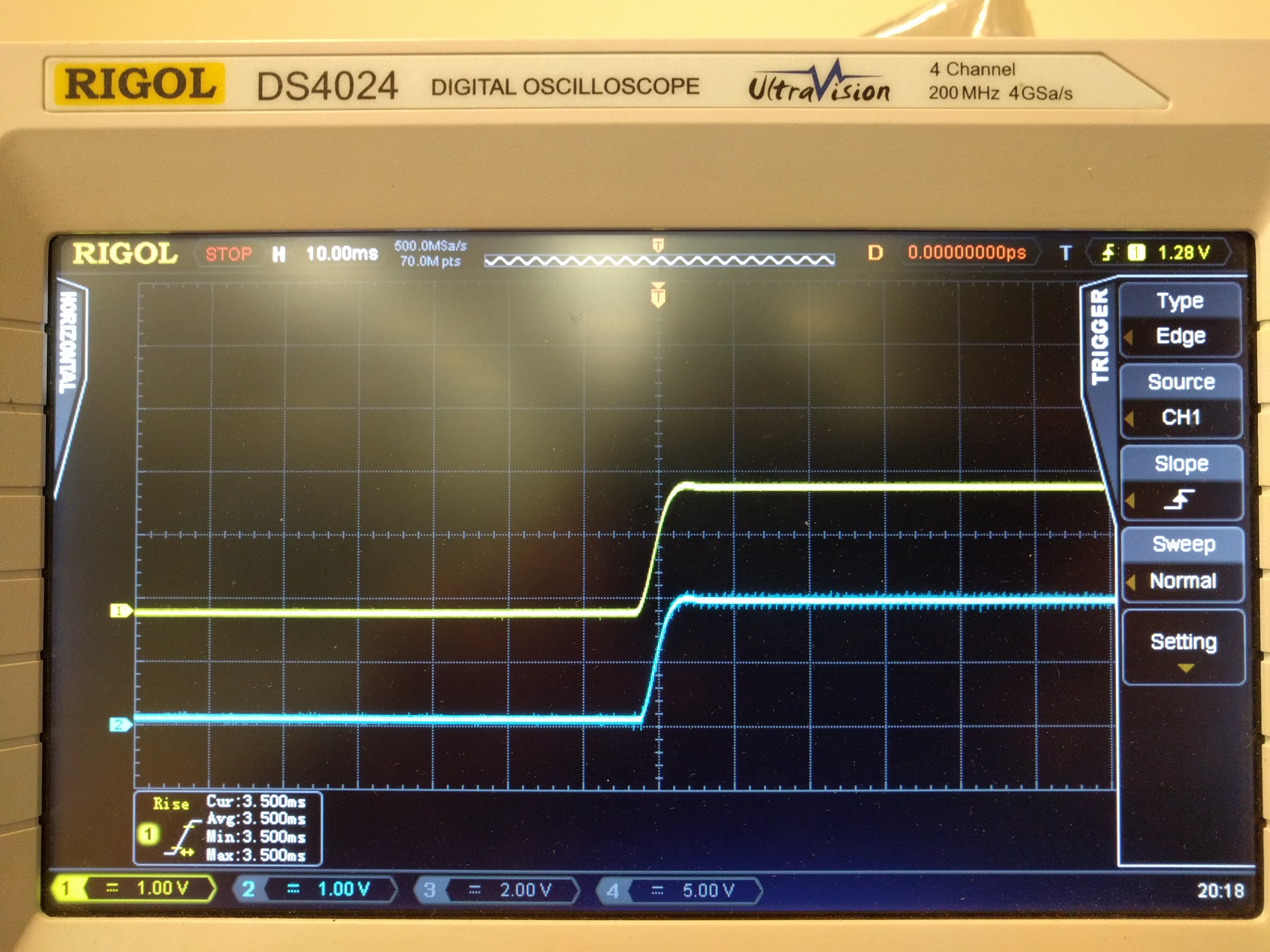
Initially, the circuit works as I would expect and I get roughly 20mA for a 2V input to the system. As part of my testing, I repeatably short the output to ensure the circuit can tolerate the fault but after anywhere from once to 10 short events, the INA195 device fails and the output just sits around 0V. This ends up putting the OPA197 in current limit as it's not getting the required feedback voltage. I can replace the INA195 and the system is operational again.

Any ideas on why this failure may be occurring?

  • Dear Tim,

    is there any chance you could walk us through the purpose of the circuit? We've attempted to simulate your results, but fall short of the expected 20mA in the load line (we're seeing about 5nA, which leads to the output of the INA195 being about 3mV).

    When you short the device, which node are you shorting? Its possible that the shorting of the output in this configuration is causing damage to the part. The INA19X family can only tolerate 5mA of current injected into any pin. It could be that what you're shorting is causing transient currents in excess of 5mA that eventually stress the part to breaking.

    Carolus

  • Hey Carolus,

    Sorry, I forgot to mention the "OUT" symbol is what's being shorted.

    During "normal" operation, "OUT" is shorted with a DMM in current mode where I read the 20mA. I then tap the DMM probe on "OUT" to simulate someone accidentally disconnecting and reconnecting the output. This is when the part eventually fails and despite current flowing through R138, the output of the INA195 remains around 0V.

    I also attempted this same test with a 100 Ohms in series with the DMM and got the same results.

    Thanks,
    Tim
  • Carolus,

    The purpose of the circuit is to generate an output current proportional to the input voltage on U19. The configuration I've used may seem strange but there are some parts of the circuit which I didn't show. The feedback path to U19 actually goes through an analog switch to select between feeding back the voltage output from U19 directly (just a voltage follower) and the circuit that I showed. This allows me to have a current or voltage output. I didn't show these parts of the circuitry because they are not being switch/changed during these tests and I believe I can treat them as not being present.

    Tim
  • Carolus,

    Is there anything that I can run on my end to test out any suspicions? I'm eager to come to a resolution here and I'm a little stumped as to what might be going on.

    Thanks,
    Tim

  • Dear Tim,

    Sorry for the delay, we've been discussing your circuit on our end. Is there any way you could provide us the total circuit, switches included, and also, possibly, your layout?

    A question we had was are you attempting to power cycle after failure to see if the problem is some form of latching condition in the circuit? We know that the feedback loop is broken after the event, but do we know the INA195's are damaged after your test? Brass tacks: is what's happening in the circuit breaking the parts?

    As for tests on your end, can you get scope shots of the input pins of the INA during one of the shorting events? We speculate that what is happening is during the event, transient currents in excess of 5mA are traveling through the part, which eventually are causing the part to fail, as this is one of the absolute maximums that must be observed by the device. This is more than likely due to the OPA railing the load line to 10V when the feedback loop is broken. A potential fix, if this is the case, is to place common mode capacitive filters on the input lines of the INA to help slow the response on the line. Current limiting resistors placed on the input lines could also help mitigate the problem, but will contribute to the gain error of the part, which leads me to ask: how much accuracy do you need in the system?

    Carolus

  • Carolus,

    Is there a way to share that information offline?

    That's interesting what you say about power cycling the circuit. I hadn't purposefully power cycled the circuit to see if the circuit was able to recover. You were right, the part comes back and doesn't appear to actually be damaged.

    I will grab some scope traces for you but I can't right now. We only have one scope here and it's away until Monday.

    Thanks,
    Tim
  • Dear Tim,

    Clarifying your test method, you're saying that you have your ammeter running to ground, and the system works fine, but then you short the leads of the ammeter together, picking the lead from ground up to do so, and that is when the system breaks? So it's during the event that OUT is un-loaded that the system breaks? This would make sense, as with no path for current to flow, the shunt differential would become zero, which bricks the feedback as you say.

    However, you say you still measure current through the shunt resistor after you return the ammeter lead to ground, but see no voltage on the INA output? How much current are you seeing when you replace the probe? Can you also probe the differential and see what voltage you are seeing across the shunt?

    You're probably seeing a latchup condition in one of the parts due to the loss of feedback in the OPA. This is causing the part to amplify the positive input by its open loop gain, and rail to 10V. However, I don't know at this point if the latchup is happening in the INA or the OPA.

    I will check in with the op amp team as well, as they will be able to help provide additional support on the OPA167.

    In the meantime, one of our application engineers recommended you look at the attached simulation, as it presents a circuit that might circumnavigate the issue you're seeing during this event by providing local feedback to the amplifier even when the output is open. It is also recommended that you still look at common mode caps to help control the rise of the signal into the INA.

    switching_shunt_current.TSC

  • Carolus,

    Yes, your description of my test is accurate.

    The output current is ~65 mA and the differential voltage is ~65 mV while the output of the INA is 0V.

    I'll take a look at the suggested circuit and get back to you there.

    Thanks,
    Tim

  • Carolus,

    I'm not sure I understand the benefit of the proposed circuit aside from it preventing the OPA from going open loop. By going open-loop are we at risk of latching up?

    I should also mention that the circuit needs to output a current proportional to the input voltage regardless of the "OUT" load. This would assume the load is of small enough resistance that the OPA doesn't saturate on the positive rail.

    I'm eager to get the scope back in the office (have to wait for Monday) to see the transients on the INA inputs. I can also at that time look at adding to the common-mode capacitor and series resistance as you suggested to the INA to see if that solves the issue.

    Thanks,
    Tim
  • Dear Tim,

    I sent you a friend request with my email. Could you send me your schematic off forum just to make sure we've got a total picture. I'm also looking into getting the parts needed to try and recreate the issue on my end here.

    The benefit of the circuit I presented is that you can control the magnitude of the step response when the output becomes opened. It sounds like the part is not being able to drive the open loop output to 10V anyhow.

    Finally, what are the purpose of C80 and R137? Are they part of your feedback loop, or were they meant as filtration on the output line? It might not be latching, it could possibly be a stability issue in the feedback.
  • Carolus,

    C80 and R137 are to stabilize the over all control loop with the OPA and INA. I did notice today while going through the datasheet that I may have incidentally destabilized the INA with the size of capacitance. I definitely need to probe a little closer with the scope, I thought I had the scope on the INA during the fault but I can't remember for sure.

    I'm sending over the schematic now.

    Thanks,
    Tim
  • Carolus,

    One correction to my original post, V_PWR is actually 15V not 10V, my apologies.

    I was able to take some scope traces this morning.

    Figure 1. CH1 (yellow) is on the INA + input and CH2 (blue) is on the INA - input. This is what happens during my fault tests.

    Section 1. The OPA and INA are regulating the output current at 20 mA as expected.

    Section 2. Ammeter probe is lifted up.

    Section 3 and 4. Ammeter probe is being reattached.

    Section 5. OPA and INA are no longer regulating as expected, OPA is in current limit.

    The three diagrams following the first are zoomed in captures of the various events.

  • I also did some other investigation. When I settled on 100 Ohms and 22 nF for R137 and C80 to stabilize the loop, that was done through simulation with the intent of adjusting during actual test. I thought it might be interesting to remove those components and see the results.

    First, I scoped the input to the OPA (CH1) and output of INA (CH2) before removing the components.

    Then, the same thing with the components removed:

    Now, interestingly, I can't get the output to fault in this configuration which leads me to believe that maybe I'm overloading the INA output with the 22 nF capacitor. I'm going to adjust my components so that the capacitance is lower and see if I can both: stabilize the loop and prevent overloading the INA.

    Please let me know if you have any other suggestions. At this point however, I'm putting off with the INA input caps unless you think this is still the issue.

  • Dear Tim,

    I'd be inclined to agree with you. Since the maximum capacitive load of the INA is 10nF, it may have some bearing on the situation.

    As for the common mode caps, they would simply be to control the rise time on the input side. I would say you're on to something with the capacitor in the feedback loop, and start there.