This thread has been locked.

If you have a related question, please click the "Ask a related question" button in the top right corner. The newly created question will be automatically linked to this question.

INA138: How to select Rs?

Part Number: INA138


Dear,

We use INA138 to detect the current, when we choose 0.001 ohm Rs, and when the surrounding DC-DC dose not work, the voltage of Rs and the output voltage of INA138 increase as the current increases. When the surrounding DC-DC works, the voltage of Rs also increases as the current increases, but the output voltage of INA138 can not increase as the current increases.

So we choose 0.01 ohm Rs, it seems that INA138 can work normally no matter whether DC-DC work or not. Now, we want to know why surrounding circuit can affect the output voltage of INA138 when the voltage of Rs maintains the same value. Thank you!

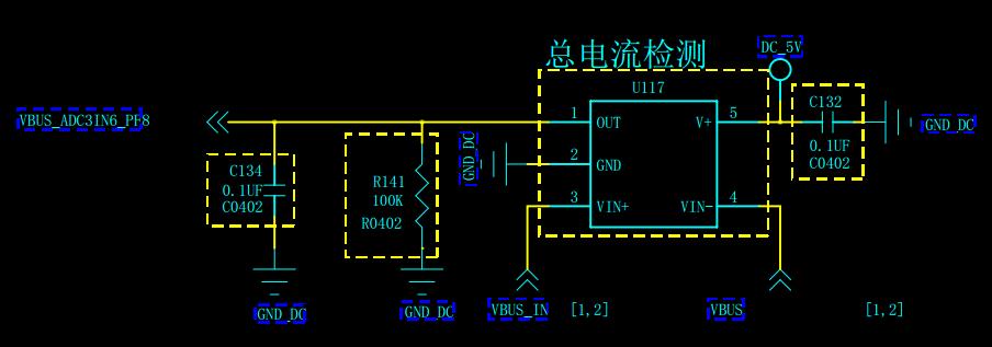
Note: the circuit of INA138 as follows.

  • Hi Shaw,

    Shaw Wong said:
    and when the surrounding DC-DC dose not work,

    Please elaborate what you mean by this statement? Perhaps can you complete schematic (Rs) shows how B+/GND connects to INA138 VIN+/-?

    We don't use INA138 but have some time with 282/240. Notice C134 (0.1uf) another INA post in forum say causes ringing on output from adding to high capacitance.

  • The INA138 is a current output device and so it behaves a little differently than our voltage out devices in terms of driving capacitive loads. The circuit implementation here is a typical filter for this device, shown in section 8.2.2 of the data sheet. The 100k load, R141, sets the gain of the device to x20.

    I also don't totally understand what you mean by the DC-DC doesn't work. Are you saying the power to the part is off? That said, I'm not sure why increasing the shunt resistor size would make the part work with the power off, so some clarification here is needed.