This thread has been locked.

If you have a related question, please click the "Ask a related question" button in the top right corner. The newly created question will be automatically linked to this question.

Op amp problem

Other Parts Discussed in Thread: TLV2463, OPA2373, TLV2373

Hi all,


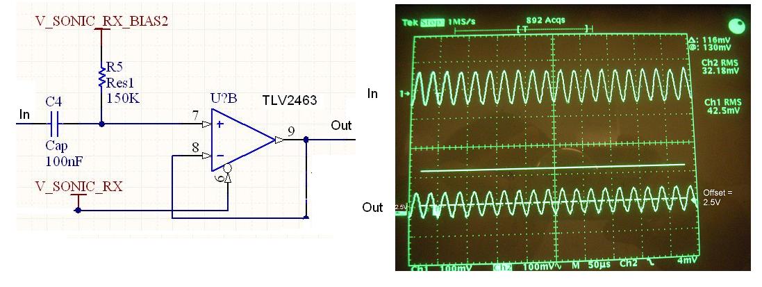
I am using TLV2463, OPA2373 as a two-stage amplifier,single supply at 3.7V, non-inverting configuration, each theoritical gain = 150. signal frequency is 40kHz (ultrasonic receiver circuitry).

Shutdown pins are directly connected to VDD.

Output of the 2nd stage is connected to a diode-RC simple peak holder circuit. 


i have some questions:

1. when it is measured, why the gain (Vo/Vi) is lower than 150.. it is around 40. 

2. stage two (2nd op amp in the IC) always get damaged eventually. no idea why.

The output of the 2nd op amp is either stuck high or smthing else (will post a picture)

what could b the problem?

  • Hi Charly.

    You have mentioned that you are using the TLV2463 and the OPA2373 in your question, but the attached schematic shows that the op amp is TLV2373.

    Can you please clarify which op-amp goes where in the schematic?

  • Hi Arvind Raj, Thanks for replying. :)

    The op amps i used are TLV2463 and OPA2373.

    Previously i used TLV2373 (lower GBW), same problems on gain happened (theoritical gain not same as measured gain, the gain was set to 75 when using TLV2373, but measured gain was much lower than that). Frequency of interest is 40kHz.


  • Content removed by author.

  • I did another experiment by using independent biasing supply to the op amp (V_SONIC_RX_BIAS1 and V_SONIC_RX_BIAS2).

    VSONIC = 3.0V

    When R5 is connected  to pin 7 of opamp 2, the voltage at pin 7  is 2.5V and V_SONIC_RX_BIAS2  is about 1.8V.

    when R5 is NOT connected to pin 7, V_SONIC_RX_BIAS2 is 1.5V. 


    This problem does not happen with V_SONIC_RX_BIAS1. the voltage at pin 3 remains the same (VSONIC/2, or 1.5V) regardless if R4 is connected or not. 

  • Here's the picture of the waveform when op amp is damaged.

    There are two op amps in one IC (TLV2463). one is OK, one is damaged. 

  • Hi Charly,


    I saw the circuit you have posted and these are my suggestions

    1. when it is measured, why the gain (Vo/Vi) is lower than 150.. it is around 40. 


    At 40kHz, the open loop Gain of the OPA2373 is around 50dB (which is around 316). The beta (feedback factor) of your circuit at 40kHz is 1/150.

    From the formula: Gain with feedback= A/(1+AB) ,

    where A=open loop gain and

    B= feedback factor,

    the gain with feedback is calculated as 100.

    So we cant expect a gain of 150 at 40kHz from this part as we will run out of bandwidth. This is the reason you are getting lower gain.


    2. stage two (2nd op amp in the IC) always get damaged eventually. no idea why.

    The output of the 2nd op amp is either stuck high or smthing else (will post a picture)

    what could b the problem?

    I see that the first stage and second stage in your circuit is exactly same except for the load.

    Can you remove the load and try the same experiment?

    Also you have mentioned that the op amp in the second stage gets damaged. Can you confirm that by testing that op amp in a buffer configuration(or any simple configuration)? I am asking you to do this because we need to know if the part is actually failing or is it something else in the circuitry which is causing it to behave like this.

    The results of the above two experiments will help us solve the problem.


  • hi Arvind,

    My previous email is the waveform without the load (peak detector). it is to show you different behaviour of the two op amps.

    here's teh waveform of the damaged op amp in bufferc config.

  • Hi Charly,


    I saw the picture you posted and it doesn't seem like the op amp is damaged. It seems to be working fine. Can you tell me why you think its damaged?

    I would like you to measure the potential at pin 7 without the 150k ohm resistor connected. Also please double check the values of the passive components in the circuit.


  •  

    I see. But why the potential at V_SONIC_RX_BIAS2 is 1.8V and at pin 7 is 2.5V while the V_SONIC_RX is 3.0V? and why is this different from the  op amp-A (1.5V on bias voltage and pin 3 of op amp-A).


    u also see the photos in my previous emails when the op amp is in non-inverting configuration. op amp A vs op amp B. the output of op amp B is different from output of  op amp A. 


    Attached is the waveform of op amps without input.

    Fig A: 150k resistor disconnected, buffer configuration.

    Fig B: 150k resistor disconnected, both input (+ and - input) are floating. 

    Fig C: 150k resistor connected, buffer configuration.


  • Hi Charly,


    I have seen the pictures you have attached. There must be some other problem in the board which is causing this weird behaviour! I dont think its the problem with the op amp. Can you ship us one of your boards?