This thread has been locked.

If you have a related question, please click the "Ask a related question" button in the top right corner. The newly created question will be automatically linked to this question.

INA226: Current measurement error with PWM motor driver

Part Number: INA226
Other Parts Discussed in Thread: INA301, INA240, ADS1013, ADS1015

Hello,

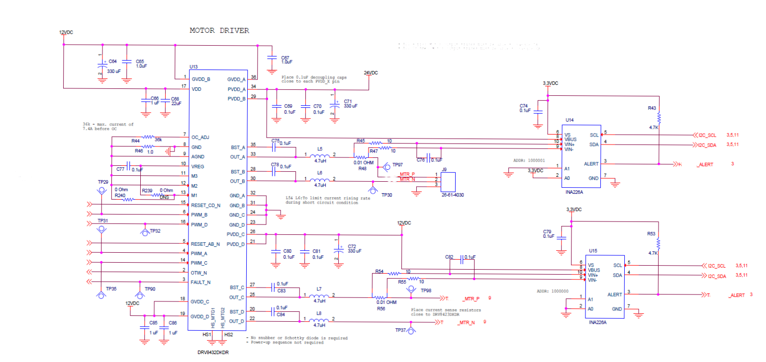
For our design the INA226 is used to monitor currents for two bidirectional motors run by a TI motor driver (DRV8432) in full bridge configuration, and the common mode voltages for the motors are 0 and 24V for one driver while 0 to 12V for the other driver during each cycle of PWM.  In the INA226 datasheet the typical common mode voltage is 12V, but the maximum value is not specified.  What is the maximum operating common mode voltage for INA226?  Is the 24V common mode voltage too large for that part?  We do not see any issues with current reading from the 12V common mode voltage motor.  However, there is a difference in the way how we run the two motors; the 24V motor runs at 33.33 kHz with a 80% duty cycle PWM while the 12V motor runs with a 99.9% duty cycle.  Our problem is that the 24V motor reads very low current (less than 50 mA) in the forward direction even though the motor runs as it should (about 500 mA).  As for the reverse direction, we read only the half of the motor current at 250 mA.

In summary I would like to find out if the 24V common mode voltage is too high and if a PWM may cause the incorrect current reading. 

Is there any other application guidance for this situation that you can offer?

Best regards,

  • Hi rainbow,

    The INA226 device common mode voltage range is 0 to 36V. A common mode voltage of 24V will work just fine. Can you please let me know what is the voltage at OUT_A and OUT_C?
  • Hi Mayrim,

    Thanks for your prompt response!  The voltage at OUT_A is 24V and 12V at OUT_C.  But, as I mentioned in my previous post, both of them are PWMed.  

  • Hi Rainbow,

    Thanks for the clarification. Unfortunately, our digital devices are not intended for PWM signals so the INA226 will not work in this configuration.
    I have 2 devices recommendations for your application:
    INA301 + ADC
    INA240 + ADC
    These two devices work well with PWM applications like this one.

    Hope this helps!
  • Hi Mayrim,

    Thanks for your response.  Indeed, it's very unfortunate for us.  Could you please elaborate on why the INA226 will not work in that configuration? It's not clear to me that that part will not work with PWM applications based on its datasheet.  Or, did I miss something?

    Best regards,

  • Hi rainbow,

    When dealing with PWM signals there are 2 parameters that you need to consider AC CMRR and Settling time. The best current sense device in the market for PWM signals at the moment is the INA240. The INA240 have a AC CMRR @ 50Khz of 93-dB and a settling time of around 10us.  These parameters are not available in INA226 datasheet as it was not designed to target this type of applications. The settling time of the INA226 might be around the ms range, I am not sure about the real value because this have not been characterized. 

    If you like to consider the INA240 device I can always revise your new schematic and offer further support. Let me know how I can support you. 

  • Hi Mayrim,

    Thank you so much for your help! We are looking into using the INA240 that you recommended with an ADS1015 or ADS1013.

    Best regards,