This thread has been locked.

If you have a related question, please click the "Ask a related question" button in the top right corner. The newly created question will be automatically linked to this question.

LMC6041: Noise characteristics of very high gain (100Tohm) transimpedance amplifier

Part Number: LMC6041

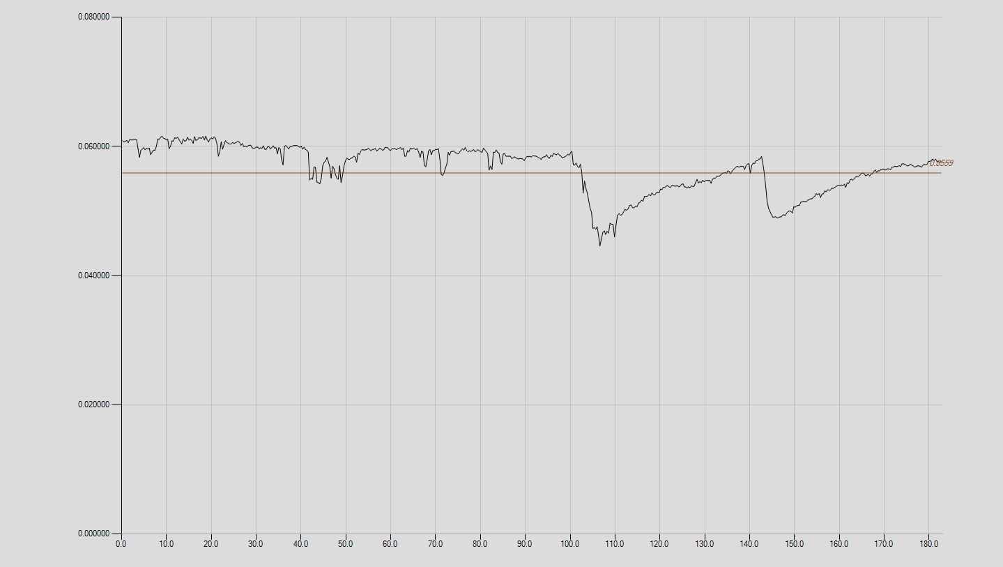
The LM6041 is used as input IC for very high gain (100Tohm) transimpedance amplifier. The noise characteristics vary between different ICs, some showing very low noise and others much noisier with large transient jumps. Need to know whether these devices are subject to some form of 'popcorn' noise or similar. Noise plots over long times are available showing these effects. If it becomes necessary to select 'good' ICs from a large batch what may be a suitable configuration for such a measurement?

  • Hi Scott,
    Scope and / or Network Analyzer plots would be very useful, if you can attach?
    Simplified schematics as well, would help.

    I'm not aware of any other technique other than the wait-and-see approach you seem to be using since popcorn noise events are random and unpredictable. However, in general the LMC6041 should not exhibit this type of noise and that's why I asked for more details.
    I also like to know the nature of your 100Tohm resistance. Is that a physical resistor because it's higher than anything else I've ever seen!

    I'll wait to see your details.

    Regards,
    Hooman
  • Dear Hooman,

    The circuit is effectively a straightforward transimpedance amplifier but has a RC zero-pole compensation network in the feedback path for the inherent feedback capacity across the feedback resistor. The resistor is a Welwyn type 3812 glass enclosed (100Tohm) resistor. The LMC6041 is the (inverting) input IC running on low noise +/-4.8V regulated supplies and there is an additional OP37 non-inverting (low-pass) amplifier in the loop with gain +5. The measured overall bandwidth is about 160mHz. The input node is PTFE insulated and the 6041 is mounted upside down with air insulated inverting pin connection to the input. I attach two plots of baseline output: B34_14MAR17NSE1.png shows a long scan with each point the average of 20 measurements at interval of 14ms and shows very low noise to start with but then a sudden increase to a higher level. The second scan (B34_24MAR17NSE1.png) over a shorter interval shows low noise but with two large deviations which prompts me to enquire about 'popcorn' noise. The rather rounded shape is due to the restricted bandwidth of the system. The general argument for going to such high gains is that at these gains the noise is primarily Johnson noise from the feedback resistor and this increases as root R whereas the signal gain increases as R so the S/N ratio improves as root R. This holds with increase in R until limited by shot noise arising from the IC bias current, and this may be where the influence of the IC arises. Some difficulty attaching second plot so this will be posted separately.

  • Dear Hooman,

    Second plot seems to have got lost so repeating :

  • Scott,

    Popcorn noise is rare on CMOS op amp. In a previous case on a similar device, the popcorn noise came from from the high value resistors.
    I suggest finding systems with highest noise and lowest noise. Swap either the resistors or the op-amps between systems and see if the noise follows the op-amp or the resistor. Show extreme care that resistor sees no physical stress in the change. Not that I think the resistor will break, but I suspect that any stress will change the noise profile.