This thread has been locked.

If you have a related question, please click the "Ask a related question" button in the top right corner. The newly created question will be automatically linked to this question.

LM7372: LM7372IMA/NOPB

Part Number: LM7372
Other Parts Discussed in Thread: UA747

Hi,

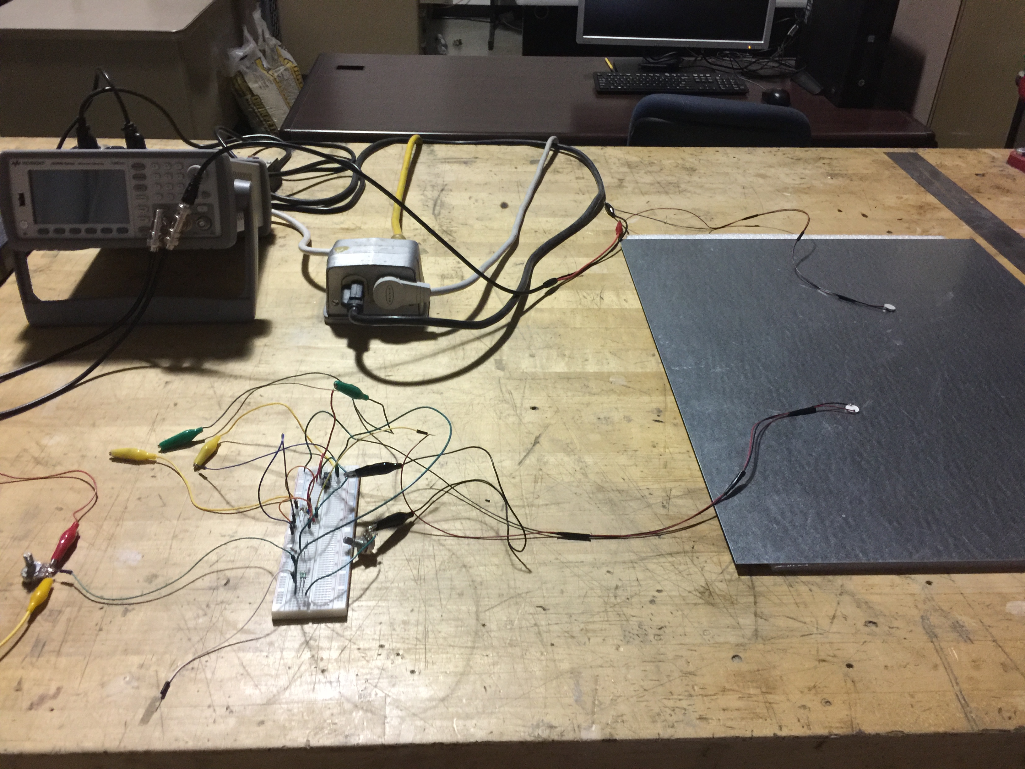
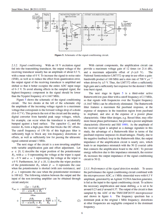
I have been trying to build attached circuit on a breadboard. First I wasn't able to find the OP Amp locally and I ended up buying an equivalent item which was ua747cn. 

But the circuit didn't work and I ordered item# LM7372 IMA but I have two issues.

1- The legs of this OP Amp are so thin and I can't insert it on the breadboard. I ended up soldering the legs.

2- this circuit still doesn't work even with this Amp. 

Can somebody help me on this?

Regards,

Mehran 

  • Hi Mehran,

    In order to get some useful help, you'd need to specify your circuit's performance and your evaluation results,i.e. scope photos, node voltages, etc.

    The LM7372 pin size is documented towards the end of the datasheet. Please make sure that the pin dimensions match the datasheet and post again if not?

    There are significant differences between the LM7372 and the ua747 that you've noted. However, I cannot comment if these differences matter in your situation or not, until we find out what you've measured on your circuit.

    So, please provide these details for better support.

    Regards,

    Hooman

  • Hi Hooman,

    Thanks for prompt response. 

    Here is the detail of what I want to do. 

    I have two piezoelectric that one is working as a transmitter and the other one as a receiver. 

    By a function generator, I am sending burst mode sinusoidal waves with frequency of 300 KHz and amplitude of 10 V_pp to the transmitter. 

    Both PZT are on a stainless steel plate. since the plate is homogeneous some of the waves will be captured by receiver. BUT, the amplitude of received signals is very low (~ 0.05 V_pp). Therefore, I need to amplify the received signals in order to have a larger amplitude as my output. I expect to amplify the signal at least up to 2 V_pp. 

    I also attached a picture of  the circuit I built in the lab for your review. 

    last thing Just to verify, all LM7372 Op Amp pin sizes are the same? 

    I hope this is clear. Let me know if you need any further information. 

    Thanks for all your help. 

    Regards,

    Mehran 

  • Hi Mehran,

    The schematic you've shown has a gain of 10x. So, with 50mVpp input, you can only expect to see about 0.5Vpp at the output. So, you'd need to increase your overall gain by a factor of 4x (for 40x total gain) to get 2Vpp. Is that why you're saying your circuit does not work? If so, then it's a matter of increasing the R5 / R4 ratio to 40 instead of 10.

    If your issue is not gain and you're measuring something else, please specify accordingly.

    Your setup is less than optimal with all the long wires, and less than optimal interconnects and not have having a ground plane. I highly recommend that you instead build your circuit on a copper clad PC board which can serve as a ground plane while maintaining minimal trace / component lead lengths. The ultimate would be an actual dedicated PC board which has been optimized for this purpose. With the setup you've shown, I suspect that you're seeing lots of interference and spurs and noise.

    For the signal you've explained, you would want to use a low noise amplifier having a Gain Bandwidth Product of at least 10MHz or higher. However, you'd not get to properly evaluate this circuit unless you clean up the bread board and use a more precise technique, as outlined above.

    The LM7372 pins are all the same dimension.

    Regards,

    Hooman

  •  Hi Hooman,

    Thanks again for the detailed email. I am attaching one page from the paper that I got this circuit from. I believe what you are saying make sense.

    One more question and sorry to bother you, I am a mechanical engineer and it is hard for me to understand some of the concepts in these circuits.

    you mentioned that " I need to increase your overall gain by a factor of 4x (for 40x total gain) to get 2Vpp"

    How can I do this?

    I appreciate all your help.

    Regards,

    Mehran

  • Hi Mehran,
    To increase the gain: An easy way would be to reduce the value of R4 (currently 10k) to 2.5k instead. That would make your gain 4x. The gain is set by the ratio of R5 / R4. Please note that I was assuming that the issue you have is "low gain" when I made this proposal (something that you've not confirmed yet!).

    Again, I think you'd need to put some effort into making your "layout" / setup much tighter and to provide a ground plane for your board.

    Regards,
    Hooman