This thread has been locked.

If you have a related question, please click the "Ask a related question" button in the top right corner. The newly created question will be automatically linked to this question.

THS4304: Used as unity gain buffer

Part Number: THS4304


Hello I've encountered myself with a board that uses a THS4304 as a unity gain buffer, and some components had to be changed (same value of components, just different lot) and the circuit started to oscillate around 900MHz to 1GHz.

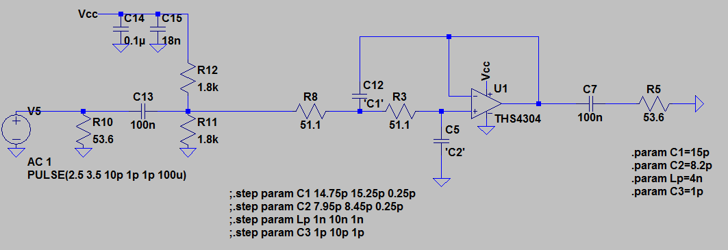
In this board the THS4304 is used as a buffer amplifier in a sallen-key cell, with Fc=100 MHz.

Is it possible that this oscillations are due to the fact thta the THS4304 is used as a unity gain amp? I´ve seen in the datasheet that all the curves are specified for G>2. 

I've also tried to simulate the circuit in SPICE, but I think the model might be not so representative because I use it in unity gain condition and I see no strange behavior.

It would be nice to have some asistance in this issue.

Best regards,

Federico

  • Hello Federico, It would be helpful if you could attach your filter circuit schematic. Also, look at figure 1 in the THS4304 datasheet and you will notice 4-dB peaking. This is generally a sign of very low phase margin and consequently instability.

    -Samir
  • The circuit is like this:

  • Hello Federico,
    I just tried this model and I do not believe it is correct. When I simulate this as a simple buffer it only gives me 0.7dB of peaking in the frequency response which doesn't seem to match Figure 1 of the datasheet. Upon further testing it doesn't look like the model includes the correct open-loop output impedance.

    Unfortunately this device is very old and I cannot seem to track down any information on the open-loop Zo. If its possible to increase the amplifiers gain that would help in making it stable.

    -Samir
  • Hello Samir,

    Yes I agree with you. Unfortunately I need more information before modifying the board. Is it possible to obtain the output impedance of the op-amp from TI?

    Regards,

    Federico.

  • Federico,
    For 100 MHz filters it is highly recommended to use passive RLC filters...in fact we use passive filters for anything above 20 MHz. The parasitics from the amplifier/PCB will cause too much variation as will the amplifiers loop gain limitations at high frequencies. Moreover non unity gain stable amplifiers are not recommended for filter design...you will end up having to noise gain shape the response which will reduce bandwidth and further and also alter the filter characteristics.
    -Samir
  • Hello Samir,

    First of all thank you for all the information and recommendations you gave me. 

    I have one last question, is there a way to simulate the output impedance of the amplifier? do you have measurements? Or maybe can I use a similar component for my simulation with the same open loop gain and with a spice model that includes the output impedance.

    I'm asking this in order to be able to simulate the exact conditions of my board.

    Best regards,

    Federico.

  • Hi Federico,

    I don't think we have a similar spice model for simulation with the same open loop gain that also includes the open-loop output impedance. As Samir mentioned, it would be best to use the THS4304 at a higher gain and use passive filtering at the output to achieve an overall system gain of 0-dB and fc = 100MHz.

    Best Regards,

    Rohit

  • Hello Rohit,

    Thank you and Samir for the answers.

    Best regards,

    Federico.