This thread has been locked.

If you have a related question, please click the "Ask a related question" button in the top right corner. The newly created question will be automatically linked to this question.

OPA376-Q1: About system configuration

Part Number: OPA376-Q1
Other Parts Discussed in Thread: OPA376

Hi All,

For consumption current reduction, I'd like to use OPA376-Q1 as follows.

Is it all right ?

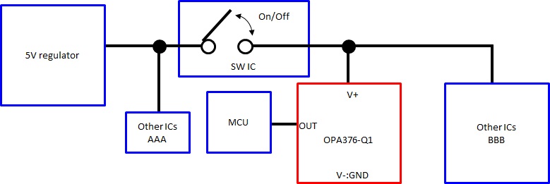
Is it possible to input V+ continuously ON / OFF?
On time: 250 μs
Period: 5 ms
Rise time: 1 us
Fall time: 1 us
V+=5V
V-=GND
+ IN and - IN are applied voltage.


Also, how long will it operate normally after applying 5 V to V+?

Best Regards
Koji Hayashi

  • Koji,

    Yes, you may turn off power supply voltage to OPA376 with a switch as shown in your diagram.  However, we have not characterized the power-up time and thus you would have to check it yourself in your specific application - but it may take few hundred microseconds for the part to properly bias up before it may be used.

    Also, opening the SW IC switch will float OPA376 positive supply.  Thus, in case of applying input voltage at +IN a volt or more above the negative supply will cause forward-biasing of the ESD input protection diode between input and (floating) positive rail as shown in Fig 2 below; this in turn will effectively cause the quiescent current, IQ, to be sourced by the input voltage source but otherwise cause no problem.  However, if the output of OPA376 has a heavy load connected as shown in Fig 3, it will cause an excessive current to flow thru ESD diode – notice that the max input current is limited to 10mA as shown in the Absolute Maximum Ratings table below.  For that reason, you must limit the input current by adding Rin resistor as shown in Fig 4.