This thread has been locked.

If you have a related question, please click the "Ask a related question" button in the top right corner. The newly created question will be automatically linked to this question.

OPA330: Active Filter Roll Off Differs From Simulation

Part Number: OPA330

Hi all,

Recently I have been testing the two filters that I have designed in the lab however I don't get the same results as the simulation

in TINA and I can't work out why.  Below are the two filters and AC responses in TINA.

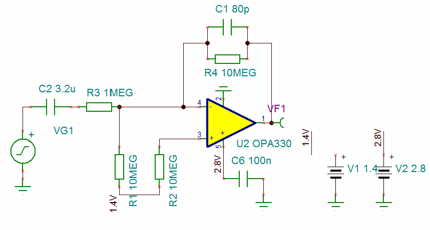
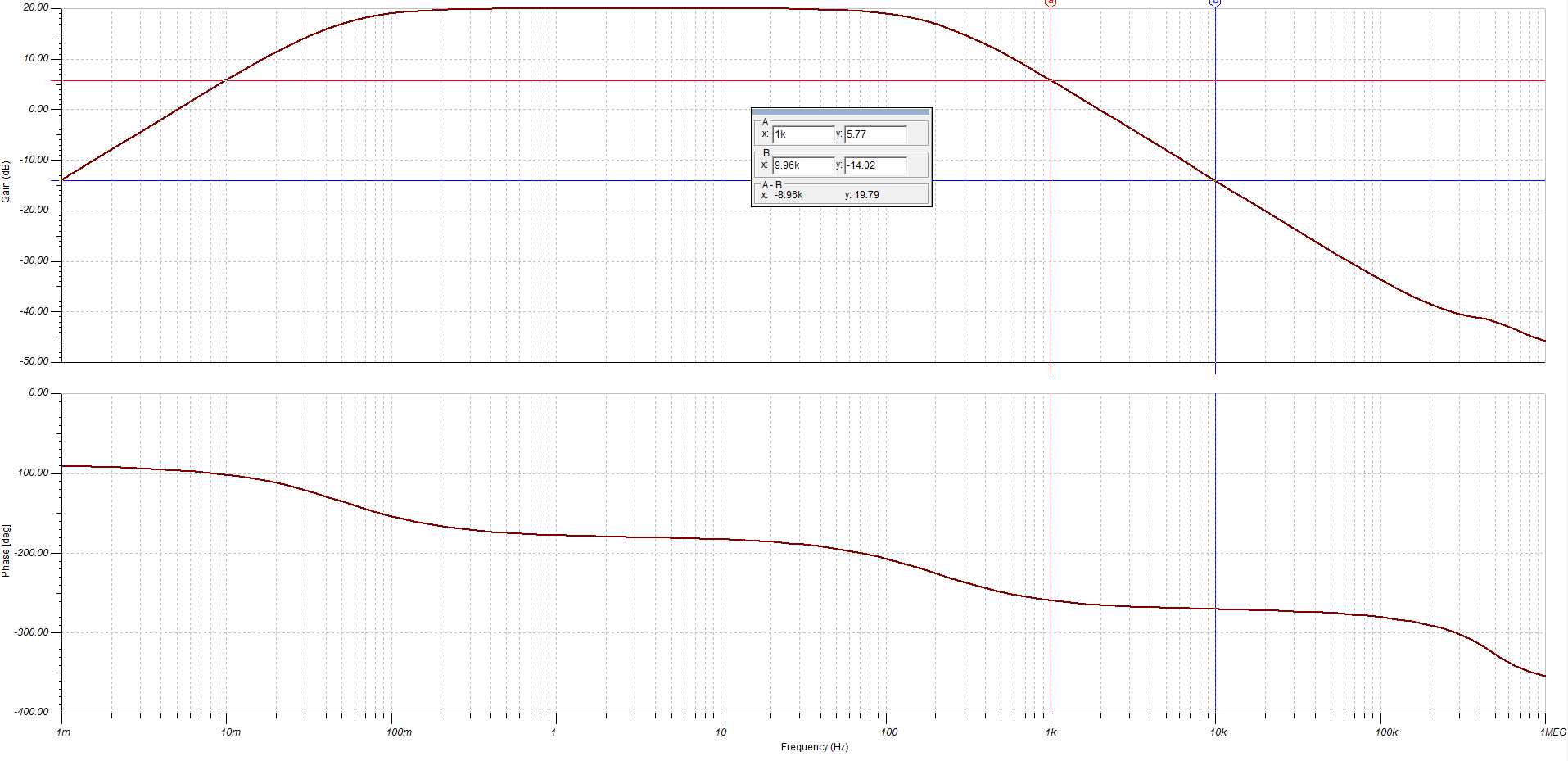
The first filter is a 2nd order Bandpass filter with cutoffs at 0.005 and 200Hz. I am expecting a roll of 20dB/dec but I am only getting 15dB/dec.

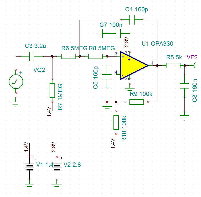
The second filter is a Sallen-Key filter with a bandpass filter attached to it. So in total a third order low pass and first order high pass.  The cutoff frequencies are at 0.05 and 200.

In the low pass region I am expecting a roll off of 60dB/dec but I am only getting just less than 40dB/dec.

The only possible explanation I can think of is parasitic components are affecting the roll off, but are there any other more obvious factors that could be causing this difference in the roll off?

Sorry if the question is quite vague as I am quite new to circuit design so would appreciate any help thanks.

Regards,

Bryan Hsieh 

  • Hi Bryan,

    I checked your filter circuits with TINA and fundamentally the roll-off rates for the various slopes should be as expected. Normal first-order roll-offs are -20 dB or +20 dB per decade, second-order roll-offs are -40 dB or +40 dB per decade, etc depending on if it is a pole, or zero, causing the roll-off. To obtain an unusual roll off-off rate such as -15 dB/dec there has to be another pole, or zero, acting in conjunction with the expected pole or zero modifying the standard roll-off rate. Over some frequency range that odd rate may be observed, but eventually a normal rate, +/-20, +/-40, +/-60 dB will be reacquired.

    You are using extremely high resistances and low capacitance values in the filter branches. It only takes a few picofarads of self capacitance and/or stray circuit capacitances in conjunction with these very high resistance values to create unexpected poles and zeros in the response. I suspect that if start adding stray capacitances across the various resistors that it will alter the responses from what is expected.

    The use of the very high resistor values will have a degrading effect on the circuit noise. A 1 Megohm resistor can contribute about 100 nV/rtHz of thermal noise. That is a lot. Just how much noise there very high resistors are adding to your circuit will depend on their interconnection with each other and the equivalent resistance in the path. You can use TINA to run the noise on the filters and get some idea of what the noise performance will be.

    Regards, Thomas

    Precision Amplifiers Applications Engineering