This thread has been locked.

If you have a related question, please click the "Ask a related question" button in the top right corner. The newly created question will be automatically linked to this question.

TLC2202A: Negative input voltage not gaining properly

Part Number: TLC2202A
Other Parts Discussed in Thread: TLC2202

Hello, I'm using a TLC2202 for a simple non-inverting amplifier circuit.  My supplies are -5V and +5V.  

When my input is positive, I see the expected output.  

When my input is negative, I do not see the expected output.  

I don't have a whole lot of experience with analog designs so I'm guessing there is some device constraint I'm violating that I don't realize.

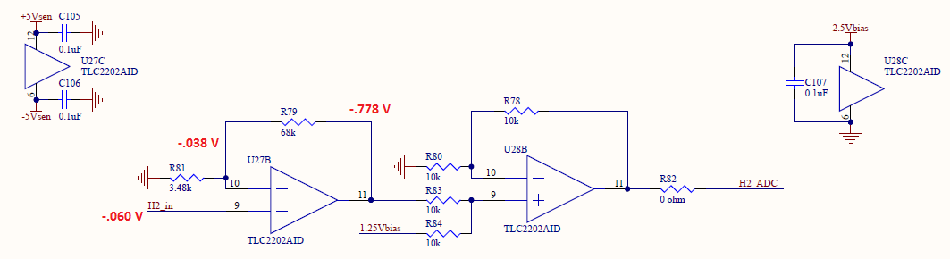
These are the voltages I measure.  Interestingly enough the gain from -.038 to -.778 is about correct, the problem is that the -.038 should be closer to -.060 in order to get my desired output.

What am I missing? Thanks!

  • Hey Matt,

    How exactly are you driving the input for your design? Has the voltage across the non-inverting pin also been measured? Also are you using two TLC packages for this design, or are both amps shown from the same package? If there are amps in your packages that aren’t being used, you may want to set those in a buffer configuration.

    Best,

    Hasan

  • Hi Hasan,

    Thank you for your reply.  I am driving the -60 mV with an independent lab supply hooked up to a voltage divider.  I'm dividing down 2.5V across about 420k and 10k resistors.  The non-inverting pin shows the -60 mV.  

    This resistor divider circuit is just for test purposes, eventually I will have a 50 ohm source sensor that will be hooked up.  I just don't have the sensor at this point.

    I am using two TLC packages for this design.  The first stage of the circuit is -5V to +5V in one chip and the second stage is 0V to +2.5V in a second chip.  I have four copies of this circuit so I am using all of the devices in all packages.

    Thanks,

    Matt

  • Hey Matt,

    Do you get a similar issue if you applied -0.06V directly to your non-inverting pin without using a voltage divider? Also, if possible, would you mind sharing oscilloscope measurements of your non-inverting node, inverting node and your output node?

    Best,

    Hasan